Features
- Measure and Source T/Cs, RTDs, Ohms, Current, Voltage
- Compact & Lightweight
- Battery or USB Powered
- Descriptive LCD Display
- 24 V Power to Drive the Transmitter
- Auto Stepping & Auto Ramping
- Selective Auto Off Mode
- LCD includes an LED backlight
Overview
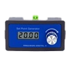
This PD9501 Multi-Function Calibrator has a variety of signal measurement and output functions, including voltage, current, thermocouple, and RTD.
Main Function
Voltage Signal: 0-30 V, 0-25 mV, 0-100 mV output and measurement.
Current Signal: Active and passive 0-25 mA, 4-20 mA output and measurement.
Thermocouple: K, E, J, T, R, B, S, N output and measurement. Note: Output Range Starts from 0°C
RTD: PT100 output and measurement.
Ohms: Output and measurement

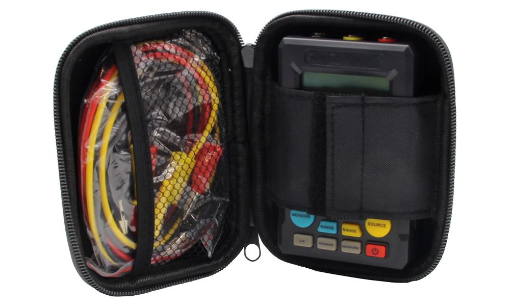
The PD9501 includes a convenient storage case.
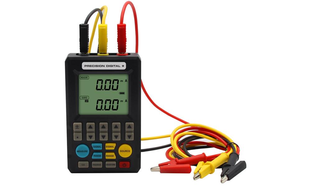
Functions

Terminal Blocks
① Common (Black)
② Output Terminal (Yellow)
③ Measurement Terminals (Red)
Buttons
④ Numeric Modifier Keys⑤ Measurement Function Keys (Blue)
[Signal]: toggle signal type
[Range]: toggle measurement range
[Measure]: open/exit measurement function
⑥ Cold Junction and Programming Function Keys
[CJC]: display/modify cold end
[Program]: turn on the programming function
[Waveform]: change programmable output waveform
⑦ [Power]: turn power on/off
⑧ Output Function Keys (Yellow)
[Signal]: toggle output signal type
[Range]: toggle output range
[Source]: open/turn off signal output
⑨ Dip Switch (Factory defaults to OFF-Down)
- Auto Power Off: 10 minutes without key operation, automatic shutdown.
- Manual Cold End: Manually set the cold end value when measuring thermocouples.
- Passive Output: outputs a passive current signal for analog transmitters.
- Low Load Mode: When the passive current is input, calibrator supplies 16 V to the transmitter to reduce power consumption and prolong the use time.
LCD Display
a: Measurement: 4 digits with unit
b: Output signal value: 4 digits with unit
c: Signal and cold end mode: 20 mV, 100 mV, 4-20 mA, K, E, J, T, R, B, S, N
RJA: automatic cold junction compensation
M: manual set cold junction compensation
d: Programming function: n/m to split the output, Output value = (Main Set Value)*(n/m)
Sweep: Linear output, Linear output signal
Step: Stepping output
Time: Output time for each step, 0-999s can be set.
Count: Output cycles, 0-999 times can be set, 0 is infinite
e: Unit: mA/mV/°C
f: Range and change function:
RL: Show the lower range limit
RH: Show the high range limit
SL: Show the minimum signal
SH: Show the maximum signal
g: Battery: Indicates battery life
Signal Output
The calibrator can output voltage, active current, passive current, thermocouple, and RTD signals.
Voltage, Active Current Output
① Connect the black wire to the common terminal, connect the yellow wire to the output terminal② Press [Signal] to toggle the signal type
③ Press
④ Press [Source], the "source" will change from OFF to ON and start the output function
4-20 mA Output
① Choose 4-20 mA for signal type② Press the opposite [Signal]. You can choose 4→8→12→16→20 or press
③ Press [Source] to open the output function

Figure 1: Output Active Current/Voltage to the meter or PLC
RTD and Thermocouple Output
Note: On thermocouple, the output temperature is minus the voltage value corresponding to the cold junction temperature.
① Press [Signal] to select signal type. Choose from K, E, J, T, R, B, S, N, RTD, Ω② Press
③ Press [Source] to open the function
Passive Current Output
Active with DIP Switch setting
Passive current output can be used as a 2-wire transmitter simulator for loop testing.
① Choose 4-20 mA for signal type② Press the opposite [Signal]. You can choose 4→8→12→16→20 or press the
③ Press [Source] to open the output function

Figure 2: 2-wire Transmitter Simulator
Voltage, Current Signal Output or Measurement by Display Range (Eliminates range conversions)
① Signal type must be voltage or current② Press [Range] to select display range limit: RL, RH, S1L, SH2
③ When “RL” is selected press
④ Setup the RL, RH, SL, SH in turn
OUTPUT
⑤ Press [Range] to exit the rage setup.Press
⑥ Press the
⑦ Press [Range] to open the function
MEASURE
⑤ Press [Range] to exit the rage setup.Press
⑥ It shows the measurement or conversion value according to range
Signal Measurement
The calibrator can measure voltage, active current, passive current, thermocouple signal, and RTD.
When measure function is not in use press [Measure] to turn off the measure mode to conserve battery power.
Voltage, Active Current Measurement
① Connect the black wire to the common terminal, connect the red wire to the measure terminal② Press [Measure] to open measure function
③ Press [Signal] to toggle signal type
④ Shows value in the LCD screen

Figure 3: Measurement voltage, active current
Passive Current Measurement
① Wiring as the 2-wire or 3-wire system② Press blue [Signal] to set signal type to 24 V loop
③ Generator outputs 24 V (or 16 V when via DIP switch to low power mode)
④ Shows value in the LCD screen

Figure 4: Measure 2-wire transmitter

Figure 5: Measure 3-wire transmitter
RTD and Thermocouple Measurement
① Connect the black wire to the common terminal, connect the red wire to the measuring terminal② Press blue [Measure] to set signal type to K, E, J, T, R, B, S, N, RTD, Ω
③ Value is displayed on the LCD screen
To view or adjust cold junction temperature for thermocouple:
① Press [CJC] to display cold end temperature② If the LCD displays “RJA” the cold end is collected by the internal sensor and cannot be modified.
③ Select the “M” on the LCD to manually set the cold end value.
Programmable Output
Scaled Output Function (n/m)
The voltage, current, and thermocouple signals can be scaled by n/m.
Output value = (Main Set Value) × (n/m)
① Press② Press [Program] to open split output mode to display n/m menu
③ Set (m) from 1 to 20
④ Set (n) from 0 to 20
⑤ Press yellow [Source] to open/exit the output
⑥ Press [Program] to exit the split output function
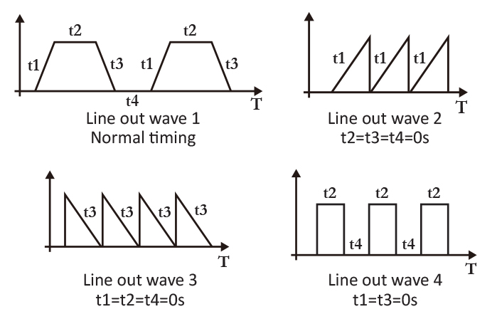
Linear Output Function
The signal value can be output linearly according to the time set by the user.
① Press② Press [Waveform] to display “sweep”. This enables linear output function.
③ Press [Program] to set output time for rise time, hold time [top], fall time, hold time [low].
Press
④ Press [Program] again to set number of linear outputs from 0-999.
⑤ Press yellow [Source] to open/exit the output
⑥ Press [Program] to exit the linear output function
Automatic Step Output Function
The signal value can be stepped out according to the user-defined value.
① Press② Press [Waveform] to display “step”. This enables step output function.
③ Press [Program] to set “time”. Press
④ Press [Program] again to set N/m for step output
⑤ Press yellow [Source] to open/exit the output
⑥ Press [Program] to exit the step output function