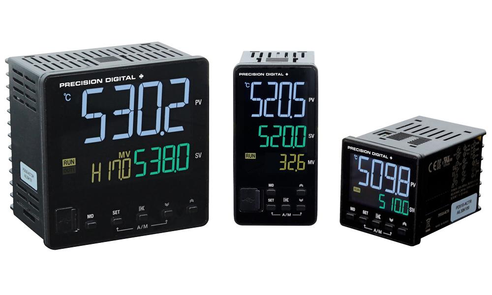
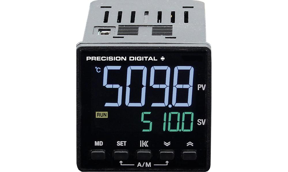
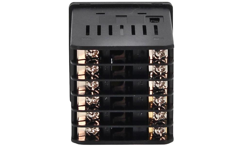
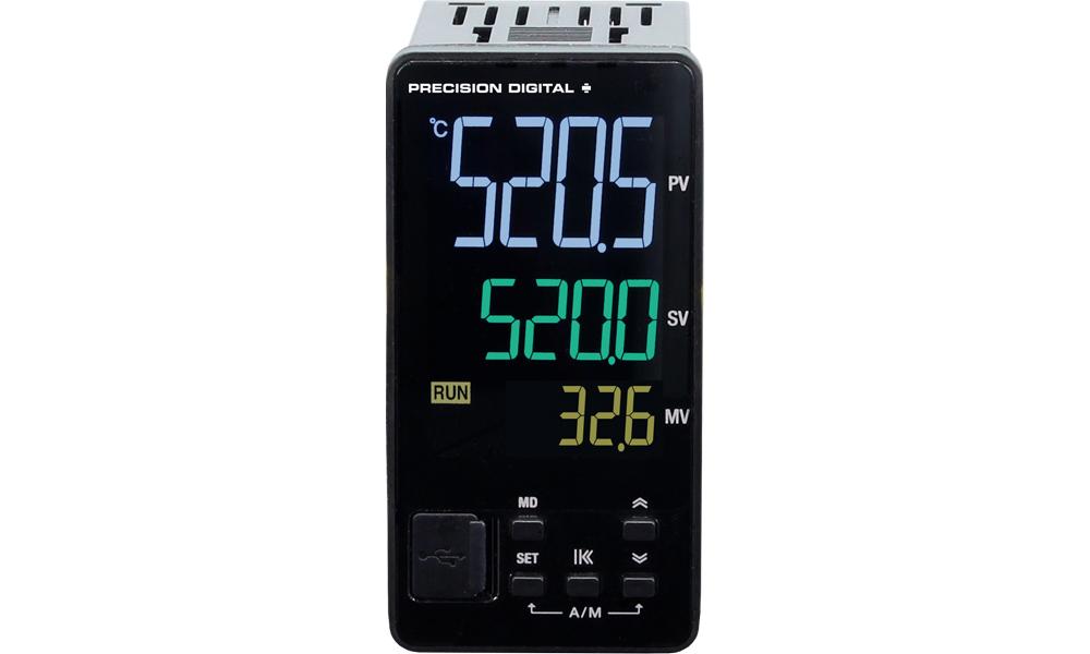
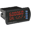
PD510 (1/16 DIN)
PD510 (1/16 DIN) Back
PD520 (1/8 DIN)
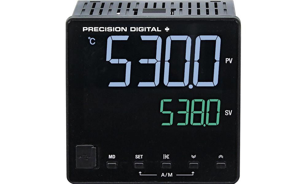
PD530 (1/4 DIN)
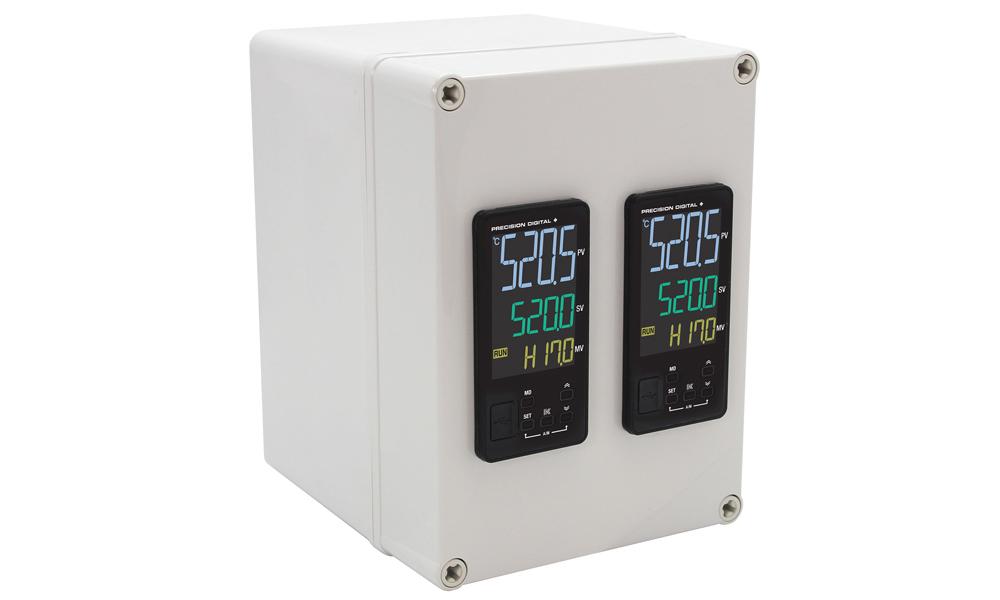
Two PD520 controllers installed in PDA2812-V (enclosure sold separately)
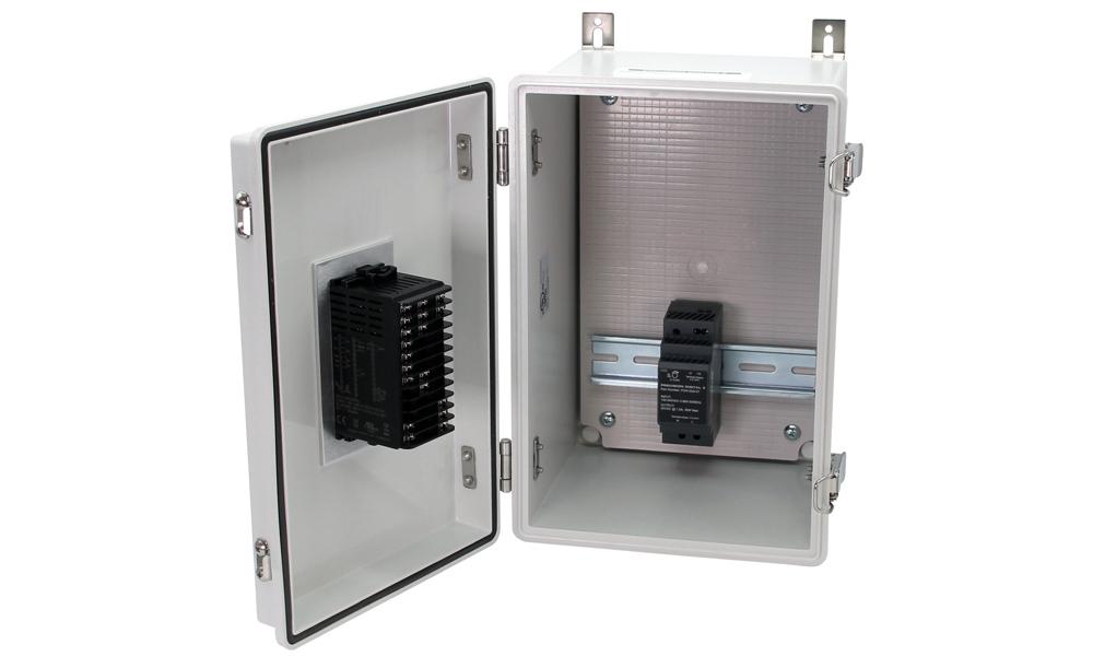
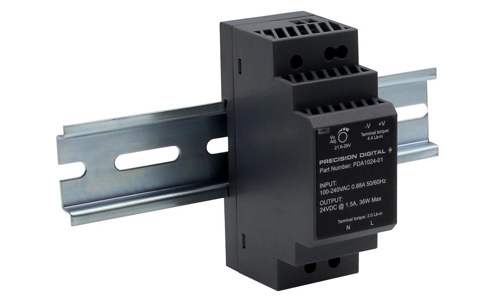
PD520 installed in PDA2301-V with PDA1024-01 power supply (enclosure & power supply sold separately)
UL RecognizedEuropean Conformity

The SuperNova PD500 Series of PID Process & Temperature Controllers are a complete line of PID and on/off controllers. Available in popular 1/4, 1/8 (V), and 1/16 DIN sizes, and with a shallow depth behind panel of only 2.5" (63 mm) they are easy to fit into almost any panel, product, or enclosure.

Voltage, current (with external resistor), and direct temperature thermocouple and RTD inputs make them an excellent choice for any control application requiring easy to change, visible set points.

This modern line of controllers shows the process variable (PV), set value (SV), and manipulated value (output level%, MV) on a striking reverse polarity LCD screen. The front panel has indicators for RUN, COM, OUT 1 & 2, REM, MANU, TUNE, and LOCK. Indicators for units (˚C, ˚F, %, or none) can also be displayed.

Changing between auto and manual control modes is accomplished by holding two buttons that are labelled SET and Down Button. A graphic on the front panel indicates that these buttons control the Auto/Manual (A/M) function:
Auto and Manual Control

The main control outputs can be a 4-20 mA (SCR), voltage pulse (SSR), or relay output. A secondary control output relay is standard, which allows for one or two direction SV control (i.e., heating and cooling).

Two alarm relays increase the utility of the SuperNova controller. The relays can be used for alarm or simple control applications. The alarms may relate directly to the process variable, or be based on deviation from the current set value.

A 4-20 mA retransmit option is available to retransmit the process variable, set value, or output level. This is especially useful for temperature inputs like thermocouples and RTDs. Other options include a secondary 4-20 mA input to remotely control the set value, and RS-485 for Modbus communication.

A mini-USB port may be used for a direct PC connection to run the SuperNova software for monitoring, programming, and data logging. This USB port is located on the rear behind the panel for PD510 1/16 DIN models, and on the front behind an IP65 rubber tab on PD520 and PD530 1/8 and 1/4 DIN models.

Features

  • 1/16, 1/8 (V), and 1/4 DIN Auto-Tuning PID Process & Temperature Controllers
  • Reverse Polarity Three-Color LCD: -1999 to 9999
  • Thermocouple and RTD Inputs
  • DC Voltage and Current Inputs (1-5 V, 0-5 V, 0-10 V, 0-50 mV, 0-100 mV; 4-20 mA with Resistor)
  • 250 Ω Resistor(s) Included Standard
  • High Accuracy Auto-Tuning PID
  • High Durability IP65 Front with Hard Plastic Pushbuttons
  • Large Easy to Read 14-Segment PV Display up to 1.1" (29 mm)
  • Input Power 100-240 VAC
  • Heating, Cooling, and Heating & Cooling Control
  • Primary Control Output Options: 4-20 mA (SCR), Voltage Pulse (SSR), or Relay
  • Secondary Control Output Relay Standard on All Models
  • Easily Switch Between Auto and Manual Control Modes
  • Up to 2 Alarm Relays & 4-20 mA Retransmit Outputs
  • Remote Set Value 1-5 V Input Option (4-20 mA with External Resistor)
  • Digital Input Set Value Selection
  • RS-485 Serial Communications Option
  • Modbus® RTU/ASCII Communications
  • Mini-USB Port Standard
  • FREE Programming and Monitoring Software
  • Shallow Depth Case Extends Only 2.5" (63 mm) Behind Panel
  • UL & C-UL Recognized Process Control Equipment, Electrical - Component

Front Panel Buttons and Status Indicators

Front Panel Buttons and Status Indicators

Easy to Read & Operate

The SuperNova PD510 digital controller has two lines with fourdigits each of white & green reverse polarity LCD digits and the PD520 and PD530 have three lines with four-digits each of white, green, & amber reverse polarity LCD digits. All can display commonly used setup parameters defined by the user.

Operating Displays & Function Keys

SuperNova Front Panel Display
Information-Packed Display
  • PV line displays process variable
  • SV line displays set value (or selectable for output value on a PD510)
  • MV line displays the manipulated value, or the output value as a %. H (heating) and C (cooling) indicated when enabled.
Front Panel Buttons and Function Keys
Function Keys
  • Hold Shift for two seconds to toggle Run and Stop modes.
  • Use SET to change the set value.
  • Hold SET and DOWN for three seconds to toggle Automatic and Manual modes.
  • Press UP or DOWN to acknowledge a latching alarm.
  • Hold SET and Shift for three seconds to Lock/Unlock the unit.

Quick Setup & Programming

Setup and programming are done through the front panel buttons or using SuperNova TCS software. After power and input signal connections have been completed and verified, apply power to the controller. There are no jumpers to set for the controller input selection.

SuperNova TCS Software

SuperNova Connected to PC for Software Programming

The SuperNova line of controllers includes the FREE SuperNova TCS monitoring and programming software. The easiest and quickest way to connect to the SuperNova TCS software is to use the on-board mini-USB port available on all SuperNova controllers. This software can be used for monitoring, data logging, programming, and troubleshooting SuperNova controllers.

Setup Group Menus

For easy setup parameter navigation, all parameters are grouped by category. To access the group menus, press and hold the Mode (MD) button for one second. Navigate through the group menus using the UP or DOWN arrow buttons. To enter a Group or change a parameter, press SET.

Parameter Group Menu

Front Panel Buttons

  • Press and hold the Mode (MD) button for one second to enter Programming Mode then press the Down (or Up) arrow button to scroll through the programing groups.
  • Hold the Mode (MD) button at any time to exit and return to Run Mode. Changes made to settings prior to pressing SET are not saved.
  • To enter a Group or change a parameter, press SET.
  • Press the Down (or Up) arrow button to scroll through individual parameters within a Group.
  • Press the Mode (MD) button when navigating parameters to return to the group menu.
  • Changes to the settings are saved to memory only after pressing SET.
  • The display moves to the next menu every time a setting is accepted by pressing SET.

Setup Parameter Lock

To prevent unauthorized changes to key parameters with pushbuttons or software, a user may lock the settings. Two levels of lock exist. Lock setting 1 locks all parameters except LOCK and the G.SV group to allow set value changes. Lock setting 2 locks all parameters except the LOCK parameter. To unlock the controller, an operator must change the LOCK parameter to off (0) with pushbuttons or software.

Easy to Use Menu Structure

Each parameter is located in an associated menu group.

Front Panel Buttons and Status Indicators

How to Read Parameters and How To
Change Parameter Values

How to Read Parameters

Process & Temperature Inputs

SuperNova Controllers use a single universal input that accepts process and temperature inputs.

Thermocouple: K, J, E, T, R, B, S, L, N, U, W, PLII
RTD: JPT100, PT100
Process: 1-5 V (4-20 mA), 0-5 V, 0-10 V, 0-50 mV, 0-100 mV
External 250 Ω resistor required to read 4-20 mA.
Recommended accessory PDX-RES2.

Versatile Operation

Powerful standard and optional features such as universal inputs, current 4-20 mA (SCR), voltage pulse (SSR), or relay control outputs, two alarm relays, two digital inputs, serial communications, and remote setpoint control make the SuperNova an excellent choice for any process or temperature control application requiring easy to change, visible set points.

Main Control & Secondary Outputs

The main control output can be a 4-20 mA (SCR), voltage pulse (SSR), or relay output. A secondary relay control output is standard, which allow for one or two direction SV control (i.e., heating and cooling).

Mini-USB Port for SuperNova Software

A mini-USB port may be used for a direct PC connection to run the SuperNova software for monitoring, programming, and data logging. This USB port is located behind the panel on the top of the controller for PD510 1/16 DIN models, and on the front behind an IP65 rubber tab on PD520 and PD530 1/8 and 1/4 DIN models.

Easy Auto/Manual Control Mode Switching

Changing between auto and manual control modes is accomplished by holding two buttons that are labelled SET and Down Button. A graphic on the front panel indicates that these buttons control the Auto/Manual (A/M) function:

Auto and Manual Control

Programmable Alarm Relays

All PD500 Series controllers have two SPST alarm relays. These alarm relays can be used for a variety of alarm and control functions and include a number of useful features.

  • On/Off Control
  • High/Low Alarms
  • Set Point Deviation Alarms
  • Loop Break Alarm
  • Latching or Automatic Reset
  • Fail-Safe and Standby Alarms
  • Alarm Delays and Wide Deadbands

Analog Retransmit Output

An optional 4-20 mA retransmitting output is available on all sizes of SuperNova Controllers.

This is especially useful when using a temperature input, to provide a 4-20 mA signal to the control room or other equipment.

  • 4-20 mA Retransmitting Output
  • Retransmit Based on PV, SV, or MV

Auto-Tuning PID

A high accuracy auto-tuning function calculates the PID values for your system with the push of a button, eliminating the need for complex PID calculations and time consuming setup. After several on/off cycles, the PID values will be setup automatically.

Simple PID Response Adjustment

The Alpha parameter allows for easily adjusting the system response without the need to change P, I, or D values.

The ALPHA parameter is used to adjust the response characteristics to the set value (SV) changes.

If ALPHA is set to 0%, it is the same as the normal PID control response.

If ALPHA is set to 100%, it may take a long time to reach a normal state, but overshoot and undershoot will be minimized.

Simple PID Response Adjustment Chart

Set Value Ramp Up/Down

When the ramp functions are used, the set value (SV) changes over time to reach a newly selected set value. When ramp functions are not used, a newly selected SV immediately becomes the active SV.

This is useful to prevent overshoot and protect equipment from rapidly changing output values as set points are changed.

Digital Input Set Point Selection

Two digital inputs can be added as an optional feature. Digital inputs are active with dry contacts or low logic levels. The configuration of the two inputs can select which set point to use (SV1, SV4, or remote) and select run and stop modes.

Digital Input Set Point Selection Chart

Normally open switches (external excitation not required) or open collector transistor contacts may be used to operate the digital inputs.

Serial Communications & Adapters

SuperNova controllers with the serial communications option include RS-485 serial communications for Modbus.

The SuperNova Controllers are Modbus server (slave) devices. Process control information can be read from the units, and setting parameters can be read or written to the controllers.

The PDA7485 RS-232 to RS-485 and PDA8485 USB to RS-485 converters are available for use with the SuperNova TCS software or other PC applications. They are especially useful with Modbus communications packages, so multiple controllers on the RS-485 bus may be accessed by computers without RS-485 communications ability.

PDA8485 and PDA7485 Serial Communication Adapters

NEMA 4 & 4X Field Enclosures

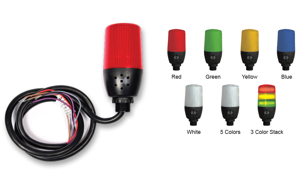
Precision Digital offers a variety of rugged enclosures that provide a high degree of protection against harsh operating environments. These enclosures are available in thermoplastic, stainless steel (NEMA 4X), and painted steel (NEMA 4). In addition, Precision Digital offers a Light / Horn that can be mounted to most of these enclosures to provide visual and audible indication of alarms. Many enclosures also have sufficient space to house Precision Digital’s model PDA1024-01 24 V power supply, signal splitters/isolators/ conditioners, and other devices.

Enclosure Selection Utility

Plastic Enclosures (Externally Mounted)

PDA2300 Series (Covers with Hinge & Latch)

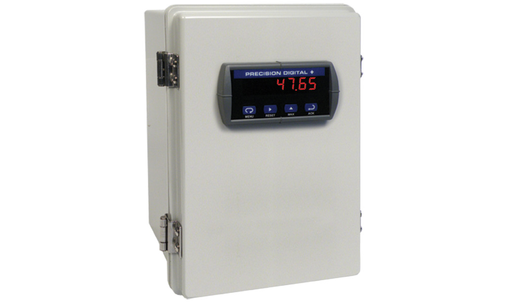
This is Precision Digital’s most economical line of enclosures for the SuperNova. The controller mounts through a hinged cover with a stainless steel latch allowing for easy access to the controller wiring. Enclosures are available for (1-2) PD510, (1-6) PD520, or (1-2) PD530 SuperNovas. The enclosure is large enough to mount the PDA1024-01 DIN rail mounted 24 V transmitter supply.

PDA2301 Enclosure

PDA2301-V Open with PDA1024-01 Power Supply Enclosure


PDA2800 Series (Covers with screws)

This is Precision Digital’s low cost NEMA 4X plastic line of enclosures for the SuperNova. The controller mounts through the front cover with four screws. Enclosures are available for (1-4) PD510, (1-2) PD520, or (1) PD530 SuperNovas.

PDA2800

Plastic Enclosures (Internally Mounted)

PDA3400 Series (Covers with screws)

The PDA3400 Series enclosures for the SuperNova fully cover the controller. The controller is fully housed inside the enclosure behind a clear plastic cover with four screws. The controller mounts in an internal sub-panel.

PDA8485 and PDA7485 Serial Communication Adapters

Stainless Steel Enclosures
(Externally Mounted)

PDA2600 Series (Covers with Hinge & Latch)

This is Precision Digital’s stainless steel line of enclosures for the SuperNova. The controller mounts through a hinged cover with a SS latch allowing for easy access to controller wiring. Enclosures are available for 1-6 PD520 SuperNovas.

PDA2600 Stainless Steel Enclosures

Steel Enclosures (Externally Mounted)

PDA2700 Series (Covers with Hinge & Latch)

This is Precision Digital’s painted steel line of enclosures for the SuperNova. The controller mounts through a hinged cover with a latch allowing for easy access to controller wiring. Enclosures are available for 1-6 PD520 SuperNovas.

PDA2700 Painted Steel Enclosures

Dimensions

SuperNova Front Dimensions
SuperNova Side Dimensions
SuperNova Dimensions Table

Panel Mounting

  • Prepare the appropriate standard DIN panel cutout. Refer to Figure 3. Panel Cutout Dimensions below for more details.
  • Clearance: allow at least 3.5" (88.4 mm) behind the panel for wiring.
  • Panel thickness: 0.04" - 0.28"
    (1.0 mm - 7.0 mm).
  • Remove the mounting bracket(s) provided with the controller.
  • Insert controller into the panel cutout.
  • Install mounting bracket(s) and tighten the screws against the panel. To achieve a proper seal, tighten the mounting bracket screws evenly until controller is snug to the panel.
    DO NOT OVER TIGHTEN, as the rear of the panel may be damaged. See Figure 1 and Figure 2.
SuperNova Panel Cutout Dimensions

Connections

PD510-A or -S (1/16 DIN)

PD510-A or -S (1/16 DIN) Connections

PD510-R (1/16 DIN)

PD510-R (1/16 DIN) Connections

PD520-A or -S (1/8 DIN)

PD510-A or -S (1/16 DIN) Connections

PD520-R (1/8 DIN)

PD510-R (1/16 DIN) Connections

PD530-A or -S (1/4 DIN)

PD510-A or -S (1/16 DIN) Connections

PD530-R (1/4 DIN)

PD510-R (1/16 DIN) Connections

Except where noted all specifications apply to operation at +25°C.

General

Display: Wide viewing angle reverse polarity LCD;
PV: white, SV: green, MV: amber
PD510: PV and SV display
PD520: PV, SV, and MV display
PD530: PV, SV, and MV display
Display Height: inches (mm)

 PVSVMV
PD5100.60 (15.2)0.29 (7.4)N/A
PD5200.81 (20.5)0.50 (12.8)0.37 (9.3)
PD5301.14 (29.0)0.59 (15.0)0.43 (11.0)
PV Display Update Rate: 4/second (250 ms)
Non-Volatile Memory: Settings stored for a minimum of 10 years.
EEPROM life: 1 million writes
Included Components: Controller with rubber gasket and mounting bracket, 250 Ω resistor (1%), and Quick Start Guide. Additional 250 Ω resistor (1%) provided for models with remote setpoint input option.
EEPROM Lock: Programmable lock or unlock write access to the EEPROM. When locked, setting changes stored in RAM (not saved on power down).
Power: 100 - 240 VAC ±10%, 50 / 60 Hz 8.5 VA max.
Insulation Resistance: 20 MΩ minimum, 500 VDC
Dielectric Strength: 3,000 VAC; 50/60 Hz for 1 minute across power terminals
Environmental: Operating temperature range: -10 to 50°C (14 to 122°F)
Storage temperature range: -25 to 65°C (-40 to 185°F)
Relative humidity: 35 to 85% non-condensing
Front Panel: IP65
Depth Behind Panel: Case extends 2.5 in (63 mm) behind panel.
Required Fuse: UL Recognized, 250 VAC 0.5 A max, slow-blow fuse.
Use fuses or circuit breakers compliant with IEC60947-1 or IEC60947-3
Connections: Fixed rear screw terminals and mini-USB
Mounting: 1/16, 1/8, or 1/4 DIN panel cutout required: panel mounting bracket assemblies are provided.
Weight: PD510: 4.2 oz (120 g)
PD520: 7.1 oz (202 g)
PD530: 10.2 oz (290 g)
Warranty: 1 year parts & labor. See Warranty Information and Terms & Conditions for complete details.

Process Inputs

Process Input Selection: Voltage or current (with external resistor)
Process Input: 1-5 V (4-20 mA), 0-5 V, 0-10 V, 0-50 mV, 0-100 mV
External 250 Ω resistor required to read 4-20 mA. Recommended accessory PDX-RES2.
Decimal Point: Up to 3 decimals.
Input Sampling: 20 samples/sec (50 ms per sample). For display update rate, see Display Update Rate
Input Accuracy:
Input TypeProg. No.DisplayScale RangeAccuracy
4-20 mA*301-5-1999 to 9999±0.2% of FS
± 1 digit
1-5 V301-5
0-5 V315V
0-10 V3210V
0-50 mV330.05V
0-100 mV340.1V
*To achieve the highest accuracy with a 4-20 mA input to the controller, connect a 250 Ω (0.1% or higher precision) resistor across the input terminals. The 250 Ω (1%) resistor included with the product is not a precision resistor. For precision resistor, order PDX-RES2.

Temperature Input

Temperature Input Selection: Field programmable for thermocouple or RTD
Thermocouple Type: K, J, E, T, R, B, S, L, N, U, W, PLII
RTD Type: JPT100, PT100
Cold Junction Compensation (RJC): ±1.5°C (-10 to 50°C)
RTD Max Line Resistance: Three wire RTD with identical line resistance up to 10 Ω
Input Sampling: 20 samples/sec (50 ms per sample). For display update rate, see Display Update Rate
Input Accuracy:
Input TypeProg. No.DisplayRangeAccuracy
K1K0-328 to 2498°F
-200 to 1370°C
±0.2% of FS ± 1 digit
2K1-148 to 932°F
-100.0 to 500.0°C
J3J0-328 to 2192°F
-200 to 1200°C
4J1-328 to 1652°F
-199. To 900.0°C
E5E1-328 to 1652°F
-199.9 to 900.0°C
T6T1-328 to 752°F
-199.9 to 400.0°C
R7R032 to 3092°F
0 to 1700°C
B8B0212 to 3272°F
100 to 1800°C
±0.2% of FS
± 1 digit
100 to 200°C:
±2.0% of FS
± 1 digit
S9S032 to 3092°F
0 to 1700°C
±0.2% of FS
± 1 digit
L10L1-328 to 1652°F
-199.9 to 900.0°C
N11N0-328 to 2372°F
-200 to 1300°C
U12U1-328 to 752°F
-199.9 to 400.0°C
W13W032 to 4172°F
0 to 2300°C
PLII14PL032 to 2372°F
0 to 1300°C
JPt10020JPt0-328 to 932°F
-200 to 500°C
21JPt1-328 to 932°F
-199.9 to 500.0°C
Pt10022Pt0-328 to 1184°F
-200 to 640°C
23Pt1-328 to 1184°F
-199.9 to 640.0°C

Control Outputs

Control Outputs: Each controller has a main control output and a secondary control relay output for two directions of control. The secondary control relay output is always used for On/Off operation.
Main Control Output: 4-20 mA output (SCR), voltage pulse (SSR), or electromechanical relay (On/Off) outputs available.
Control Type: ON/OFF, PID control
Output Operation: Programmable for reverse or direct action.
Current SCR Output: 4-20 mA linear current output
Load resistance: 600 Ω maximum ± 0.2% of FS ± 1 digit
Voltage Pulse SSR Output: 12 V ± 1 VDC
Load resistance: 600 Ω minimum
Recommended minimum cycle time: 1 sec
Relay Output: Rated resistive load switching capacity: 5 A, 250 VAC; 5 A, 30 VDC
Max switching power: 750 VA, 90 W
Max switching voltage: 250 VAC, 110 VDC
Max switching current: 5 A
Mechanical life: 20 million cycles (at 180 CPM)
Recommended minimum cycle time: 20 sec

Alarm Relay Outputs

Function: Programmable for 13 different alarm types or off.
Number: Two alarm relays standard on all models.
Alarm Relay Ratings: Rated resistive load switching capacity: 5 A, 250 VAC; 5 A, 30 VDC
Deadband: 0-100% FS, user selectable
High or Low Alarm: User may program any alarm for high, low, or high-low range operation.
Absolute or Deviation Alarm: User may program any alarm as an absolute value alarm or a set value deviation alarm.
Loop Break Alarm: User may program any SUB alarm relay as a loop break alarm.
Alarm Relay Operation:
  • Automatic (non-latching) and/or manual reset
  • Latching (requires manual acknowledge) with/without clear
  • Off (disable unused relays)
Relay Reset (Acknowledge): Automatic, front panel button, in setup parameter menu, or through serial communications
Time Delay: 0 to 999 seconds, on and off delays; programmable for each SUB relay.
Fail-Safe Operation: Programmable, independent for each alarm relay. Relay coils are energized in non-alarm condition. In case of power failure, relays will go to alarm state.
Standby Operation: Programming, independent for each alarm relay
Auto Initialization: When power is applied to the controller, relays will reflect the state of the input to the controller unless standby mode is enabled.

4-20 mA Retransmit Output

Function: 4-20 mA linear current output
Scaling Range: 0-100% of full scale
Output Loop Resistance: 600 Ω maximum load
Output Accuracy: ±0.2% of full scale ± 1 digit
0-10 VDC Output: The PD659-1MA-1V can convert the optional 4-20 mA output to a 0-10 VDC output

Remote SV Process Input

Function: Process input to remotely change SV
Input Type & Range: 1-5 V, 4-20 mA
External 250 Ω resistor required to read 4-20 mA.
Input Accuracy: ±0.2% of full scale ± 1 digit

USB Connection

Function: SuperNova software connection only
Location: PD510: Top, behind panel
PD520 & PD530: Front mounted behind rubber seal, accessible from front panel
Communication: UMS (USB Mass Storage) 2.0
Compatibility: USB 2.0 Standard, Compliant
Connector Type: Mini-USB receptacle
Cable: USB A Male to Mini-USB Cable
Protocol: Protocol: PC-LINK
Baud rate: 38400 bps
Start bit: 1 bit
Data bits: 8 bits
Parity bit: None
Stop bit: 1 bit
Communication Distance: 16.4 ft (5 m) maximum

Digital Inputs

Function: Digital Input 1: Select Run/Stop Mode
Digital Input 2: Select SV 1 or SV4/REM
Contacts: DI1 and DI2, shared common
Logic Levels: On: 1.5 V; Off: 0.1 V
Input Current: Approximately 2 mA each contact
Input Impedance: On : 1 kΩ max, Off: 100 kΩ min.
Open Contact Voltage: Open contact voltage approximately 5 VDC

Modbus® RTU Serial Communications

Communication Method: EIA RS-485 standard, 2-wire half-duplex with grounded, shielded cable
Slave Id: 1 – 99 (Controller address); 31 maximum bus connections
Max Range: 3,937 ft (1.2 km)
Baud Rate: Programmable for 4800, 9600, 14400, 19200, 38400, 57600 bps.
Start Bit: 1 bit
Data Bits: Programmable for 7 or 8 bits
Parity: Programmable for none, even, or odd.
Stop Bit: Programmable for 1 or 2 bits
Protocol: PC-LINK STD, PC-LINK SUM, MODBUS-ASCII, MODBUS-RTU
Response Time: Actual response time = processing time + (response time x 50 ms)

SuperNova TCS Software

Availability: Download directly from www.predig.com/download_software
Operating System Requirements: Microsoft® Windows® 7/8/10 64-bit (x64) or 32-bit (x86)
Minimum Hardware Requirements: Pentium 1 GHz
512 MB RAM
1 GB available hard drive space (x86)
2 GB available hard drive space (x64)
Communications: USB 2.0 (single controller only)
(Standard USB A to Mini-B USB)
RS-232 to RS-485 converter or USB to RS-485 converter
(programming, monitoring, and data logging of multiple units)
Configuration: Configure parameters of all connected controllers.
Data Log: Data log onto computer hard drive.
Data log files may be exported to HTML, .xls, .xlsx, or .pdf format as graphs or data tables.
Graphs may also be exported as .bmp, .gif, .jpeg, or .png.
Data tables may also be exported as .csv.
USB Powered: USB port provides power to the controller for programming. Apply normal power for general controller operations.

Free SuperNova TCS Software

The SuperNova line of controllers includes the FREE SuperNova TCS monitoring and programming software. The easiest and quickest way to connect to the SuperNova TCS software is to use the on-board miniUSB port available on all SuperNova controllers. This software can be used for monitoring, data logging, programming, and troubleshooting SuperNova controllers. SuperNova TCS software can connect to a maximum of 31 units when using the RS-485 communications option. A single unit can be connected via the USB connection. Click here to download SuperNova TCS Software.

Remote Programming

SuperNova TCS software allows all setup parameters to be programmed remotely from a PC and saved to a file for reporting or programming other controllers. We recommend the following sequence for getting the controller into service using the SuperNova TCS software:

  1. There is no need to apply AC power to the controller for parameter setup.
  2. Connect the controller to the PC.
  3. If SuperNova TCS software (TCS) is already installed in your computer, then double click the TCS icon or select TCS from your list of programs by selecting the PD folder, and then TCS software.
  4. If the SuperNova TCS software is not installed, follow the instructions provided below.
  5. Use SuperNova TCS software to configure the controller for your application.
  6. Disconnect the USB cable from the controller.
  7. Apply power and signal and check operation of the controller.
  8. Install the controller and put into service.
  9. Make any programming adjustments using the front panel buttons.

Data Acquisition

SuperNova TCS software provides a convenient way to collect the data from the SuperNova controller. The user can select the logging time interval. Data can be written to a file, which can then be imported into a spreadsheet or other application or viewed in the SuperNova TCS software.

Monitoring

SuperNova TCS software can be used to monitor up to 31 SuperNova controllers on a PC. The screenshot below shows SuperNova TCS software monitoring a single SuperNova controller.
SuperNova Monitor Screen

Monitoring with RS-485 Connection

SuperNova TCS software may be connected directlyto the controller using the on-board USB connector. However, if used in the application, it may be convenient to use the RS-485 connection to connect to a computer. This method is also required when monitoring multiple SuperNova controllers. To connect the SuperNova controllers with the RS-485 option to a computer, the PDA8485 USB to RS-485 Isolated Converter is recommended. One PDA8485-I may support all SuperNova controllers, up to 31 units, connected.

SuperNova TCS Installation

  1. Download the SuperNova TCS software.
  2. Read all SuperNova and SuperNova TCS instructions.
  3. Download Installation file to computer
  4. Double-click installation file to open it
  5. Double-click the appropriate setup file to begin installation:
  6. TCS-1.0.2_(x86).exe for 32-bit operating systems.
  7. TCS-1.0.2_(x64).exe for 64-bit operating systems.
  8. Follow on-screen instructions

Running SuperNova TCS the First Time

The first time SuperNova TCS is run it is necessary to set up the serial communication settings of the program. Click the Add Serial Communications icon in the upper left menu, as identified below.
Add Serial Communications
Select the communication port, protocol, baud rate, serial communications parameters, and addressed of the controller(s) connected. Once the configuration is complete, select Add Port.
Add Serial Communications
Note that for USB connections, it may be required to check what virtual com port is being used for the USB connection in the computer’s Device Manager tool. Once the port is added, the port(s) and controllers(s) selected will appear in the System menu box on the left side of the screen. The image below shows on controller assigned address 01 connected to COM4.
Add Serial Communications
To connect to the controller(s) assigned to the active port(s), click the Connect icon shown below.
Connect Controllers
When connected, the Disconnected message for the port will be replaced with a “Connected” message, and monitoring will begin for the assigned addresses.
SuperNova Connection

SuperNova TCS Main Menu

The main SuperNova TCS menu consist of various commands as show below.
SuperNova Main Menu
For a more detailed listing of all SuperNova TCS software capabilities and controls, refer to the Help selection in the Help menu for a complete software manual.

Top Level Menus

The File, Communication, and Online menus have icons that appear automatically below the menus.
SuperNova Main Menu
SuperNova Main Menu Load Monitoring Data

Open the Graph Viewer to see previously data logged information in chart or table form and export it into various file formats.

SuperNova Graph Viewer
SuperNova Main Menu Monitoring Data Saving Start

Starts data logging for the selected units in the System menu list.


SuperNova Main Menu Start Saving All the Monitoring Data

Starts data logging for all connected units on a port.


SuperNova Main Menu / SuperNova Main Menu Lock or Unlock

Locks or unlocks all the functions of the SuperNova TCS software.


SuperNova Main Menu Add Serial Communications

Opens the new serial communications menu to setup a new port.


SuperNova Main Menu / SuperNova Main Menu Connect or Disconnect

Connect or disconnect all the controllers connected a port.


SuperNova Main Menu Monitoring

Opens the graphical monitoring screen for the selected controller.

SuperNova Monitoring

SuperNova Monitoring Text Monitoring

Opens a chart listing the monitoring information for all connected controllers.

SuperNova Monitoring Chart

SuperNova Multitrend Multitrend

Opens the trend graph monitoring screen for all connected controllers.

SuperNova Multitrend Chart

SuperNova Parameter Parameter

Opens the parameter list and parameter settings for the selected controller. Changes to the parameters and setup may be done from this screen.

Parameter configurations may be uploaded from the controller, downloaded to the controller, saved as a file, or loaded from a file.

SuperNova Parameter List

Tool Menu

This menu is used to open the Graph Viewer to see previously data logged information in chart or table form and export it into various file formats.

It also contains the Settings menu. The Settings menu is used to select English or Spanish language text, and to set a password to lock the software setup from changes.


Help Menu

Use the Help selection to open the SuperNova TCS complete manual. Use the Program Info selection to view the software version information.

loader.gif

Are you looking for enclosures that are compatible with this meter?

Accessories Listing:

Choose Your Options