


Features
- 1/8 DIN Digital Panel Meter with NEMA 4X, IP65 Front
- 0-20 mA, 4-20 mA, 0-5 V, 1-5 V, and ±10 V Field Selectable Inputs
- Dual-Line 6-Digit Display, 0.6" (15 mm) & 0.46" (12 mm)
- Isolated 24 VDC @ 200 mA Transmitter Power Supply
- 2 or 4 Relays with Interlocking Capability + Isolated 4-20 mA Output Options
- Free PC-Based, On-Board, MeterView Pro USB Programming Software
- No Assembly Required
- Optional SunBright Display Models for Outdoor Applications
- Operating Temperature Range: -40 to 65°C (-40 to 149°F)
- UL & C-UL Listed. E160849; 508 Industrial Control Equipment
- Input Power Options: 85-265 VAC / 90-265 VDC or 12-24 VDC / 12-24 VAC
- Display Input in Two Different Scales - Great for Level Applications
- Multi-Pump Alternation Control
- Round Horizontal Tank Formula; Just Enter Diameter & Length
- 32-Point Linearization, Square Root Extraction and Programmable Exponent Function
- Programmable Display, Function Keys & Digital Input
- External 4-Relay & Digital I/O Expansion Modules
- RS-232 & RS-485 Serial Communication Options with Modbus RTU
- Password Protection
- Wide Assortment of NEMA 4X Enclosures for up to Ten Meters
- Light / Horn & Reset Button Accessory
- Control Station Accessory For Remote Operation of ProVu
- Stainless Steel Sun Hood Accessory Available
- 3-Year Warranty
Overview
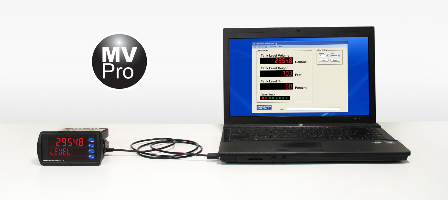
The Only Process Meter You Will Ever Need
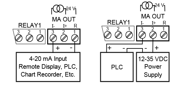
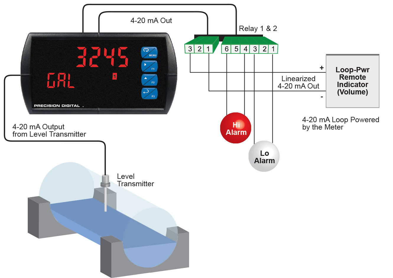
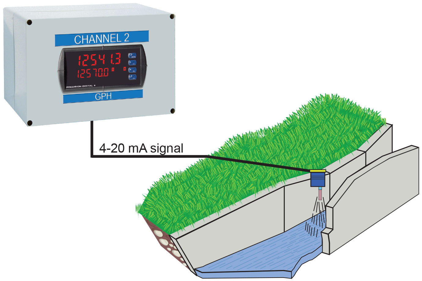
Front, back and in between, the ProVu meter boasts specifications, features and functionality that make it the only 1/8 DIN process meter you will ever need. The number one feature that makes the ProVu such a useful device is its built-in 24 VDC power supply to drive the transmitter as illustrated by the above diagram. This feature not only saves the cost of an external power supply, but also greatly simplifies wiring. In addition, there is a second 40 mA power supply provided with the 4-20 mA output option, evident also in the above diagram.
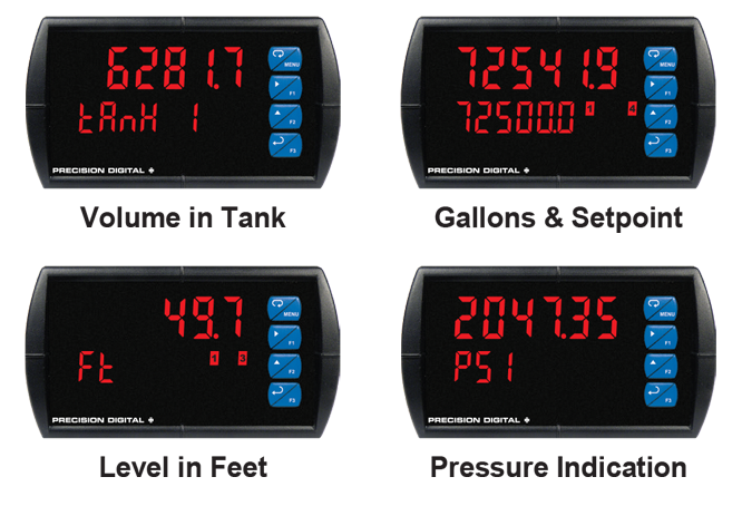
The picture above illustrates several other reasons why the ProVu is the only process meter you will ever need. First off, is the NEMA 4X rated front panel which means you can install the ProVu in panels exposed to moisture, dust and other adverse conditions. The picture also points out that the ProVu is available with an optional Sunbright display which means you can install and read the ProVu in direct sunlight. The next thing to notice is the 6-digit dual-line display that can display numbers up to 999,999 on the upper line and show either a tag or the input in a different scale on the lower line.
Other key features include four relays and 4-20 mA output option, advanced signal input conditioning like automatic round horizontal tank linearization, function keys, pump alternation capability, and Modbus RTU serial communications. Finally all these features and capabilities can easily be programmed with free MeterView Pro PC-based software.
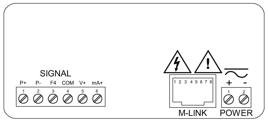
Front

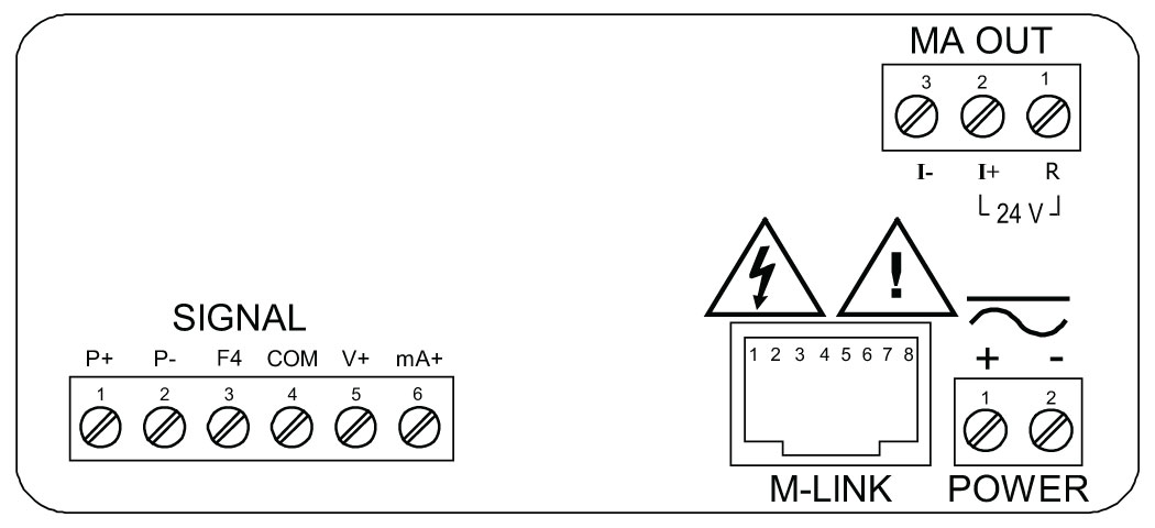
ProVu Connections

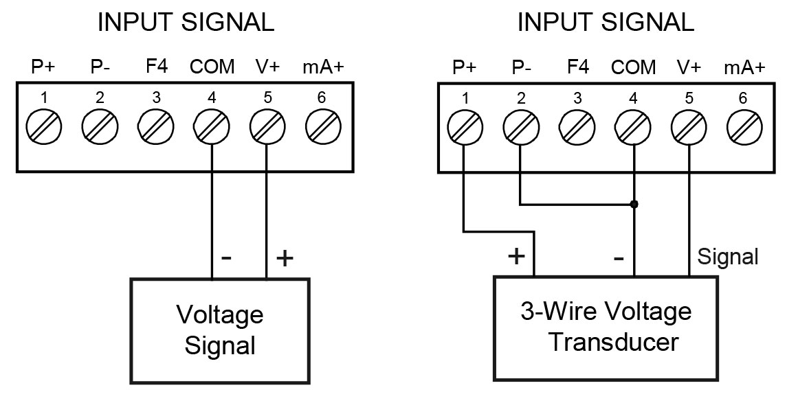
Isolated Transmitter Power Supplies
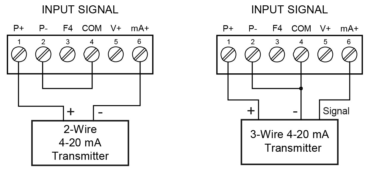
24 V @ 200 mA Transmitter Power Supply

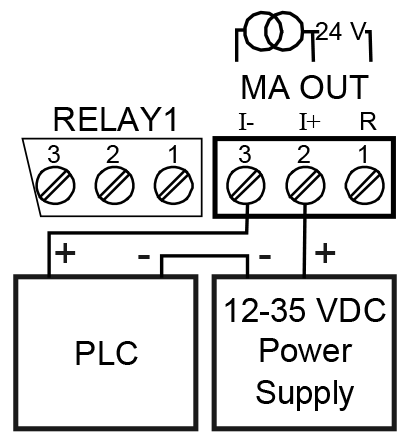
One of the most useful standard features of the AC powered PD6000 is its built-in isolated, 24 V @ 200 mA power supply to power the transmitter. This feature saves money by eliminating an external power supply and also simplifies wiring by reducing the number of devices in the loop. It can be configured for 5, 10, or 24 V (default) by means of a simple internal jumper. This power supply is even available on meters that are powered from DC power (24 V @ 100 mA). To use an external power supply instead of the internal power supply, simply make connections to different terminals on the ProVu. The following diagrams illustrate how to wire the ProVu so it will power the transmitter:
24 V @ 40 mA 4-20 mA Output Power Supply
Not only can the ProVu power the 4-20 mA input signal, but an
additional power supply of 24 V @ 40 mA is provided with the
4-20 mA output option to power the 4-20 mA output.
Resettable Fuse Prevents Current Overload
Another very useful aspect of the ProVu is that the current input is protected against current overload by a resettable fuse. The fuse limits the current to a safe level when it detects a fault condition, and automatically resets itself when the fault condition is removed.
Other Uses for Transmitter Power Supplies

The most common use for these two power supplies is for the 200 mA transmitter power supply to power the field transmitter and 40 mA power supply to power the 4-20 mA output from the meter. However, since these two power supplies are isolated they can be used in other ways. For instance, some level transmitters require the use of a heated lens. The ProVu’s 200 mA power supply could be used to power the heated lens and ProVu’s 40 mA power supply could be used to power the 4-20 mA input.
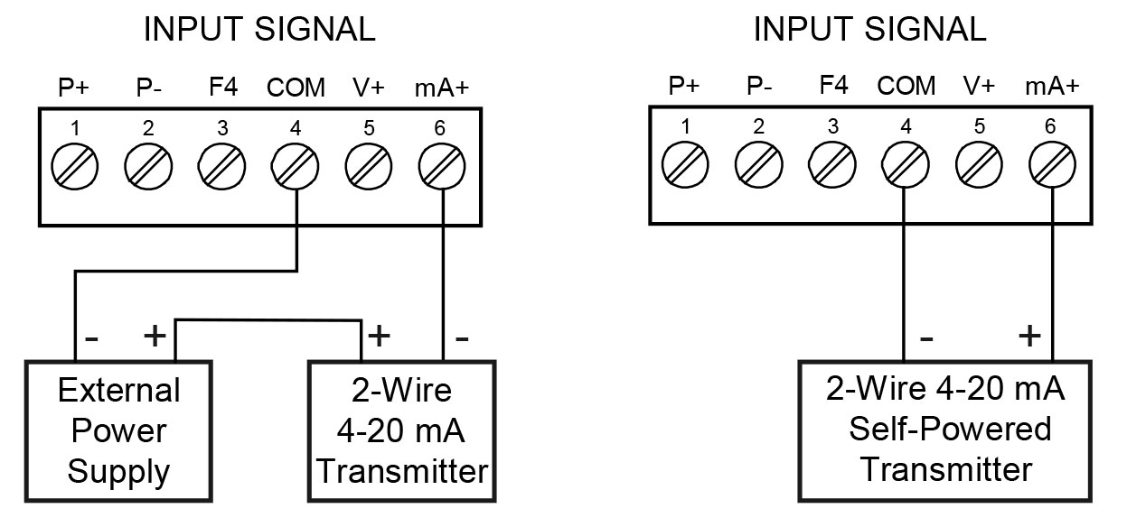
External Power Supply for the Loop

For applications that require an external transmitter power supply, the same ProVu is used and merely wired in a different fashion as the following diagrams illustrate:
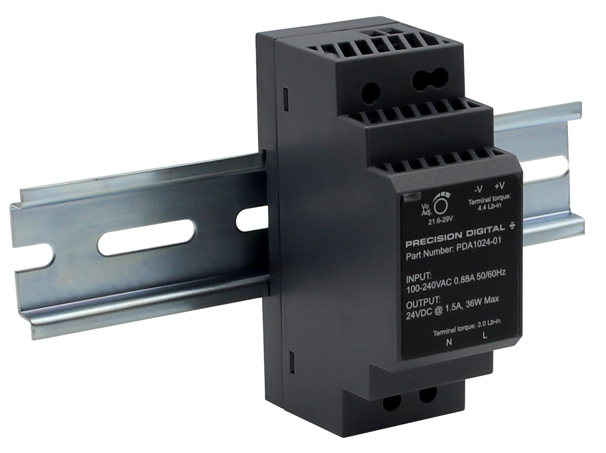
PDA1024-01 24 VDC Transmitter Power Supply
Precision Digital offers the PDA1024-01 for applications that require more than the 200 mA power that the ProVu can provide.
SPECIFICATIONS
Output Voltage:
24 VDC ±10% @ 1.5A rated current
Dimensions:
1.40" x 3.50" x 2.10"
(35 mm x 90 mm x 54.5 mm)
(W x H x D)
Advanced Display Features
Dual-Line Makes All the Difference
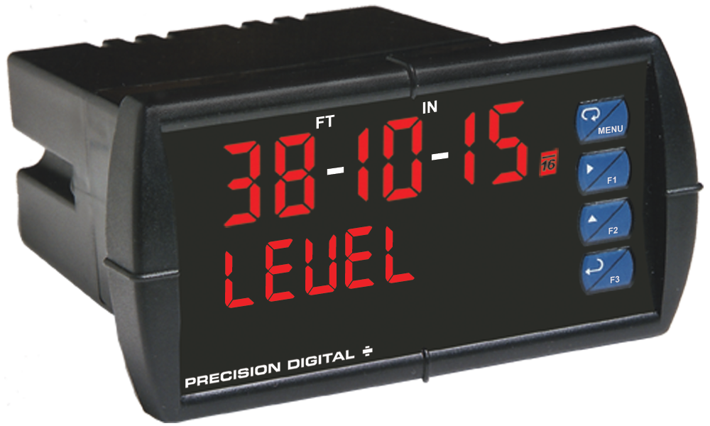
The upper display can be programmed to indicate PV, maximum (peak), minimum (valley), alternating maximum/ minimum, one of eight alarm set points, or Modbus input. The lower display can be configured to display engineering units, set points, user defined messages, or simply turned off.
The ProVu’s dual-line display makes all the difference both when programming the instrument and when using it in the field. When programming the instrument, the dual line display prompts for the needed information and also helps you keep track of where you are in the setup process. When using the instrument, the dual line display provides more information such as displaying the input in two different scales like height and volume for a level application. We call this the Dual-Scale feature.
Programming Assistance
The ProVu’s dual-line display makes programming the instrument much easier because the lower line prompts for the needed information and also helps you keep track of where you are in the setup process.
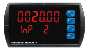
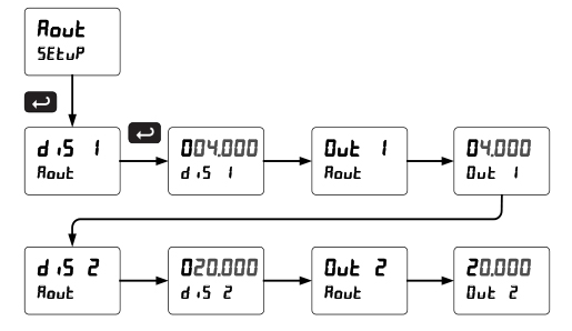
In the example above, the ProVu is prompting for the value for Input 2 and displaying the default value of 20.00 mA. The “2” in 20.00 is brighter than the rest of the digits indicating that it is the number that will be changed by the Up and Right arrows.
In the example above, the ProVu is now prompting for what the user wants Display 2 to be; that is the value that corresponds to 20 mA. In this case Display 2 is currently set to 95.00.
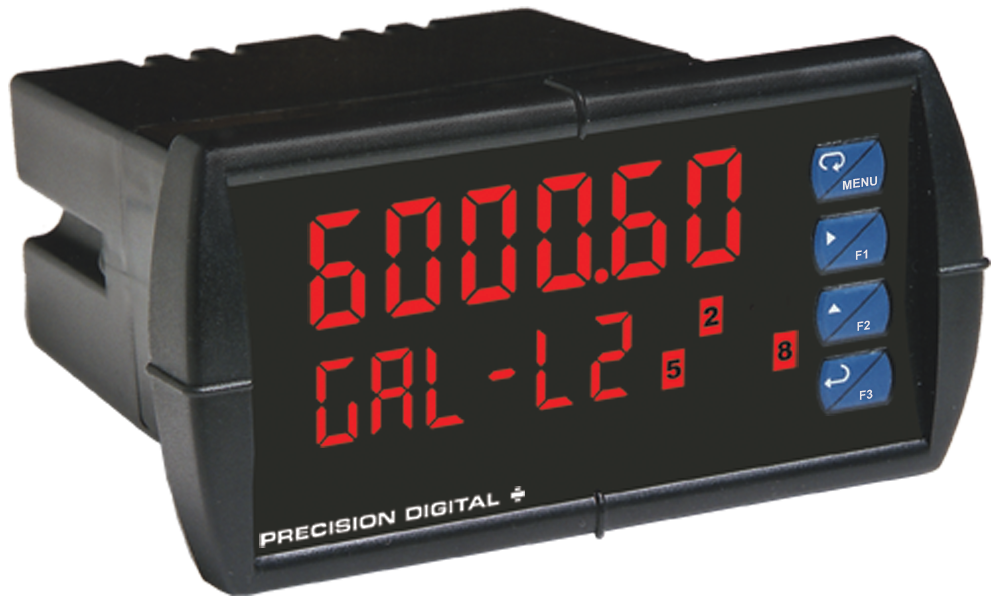
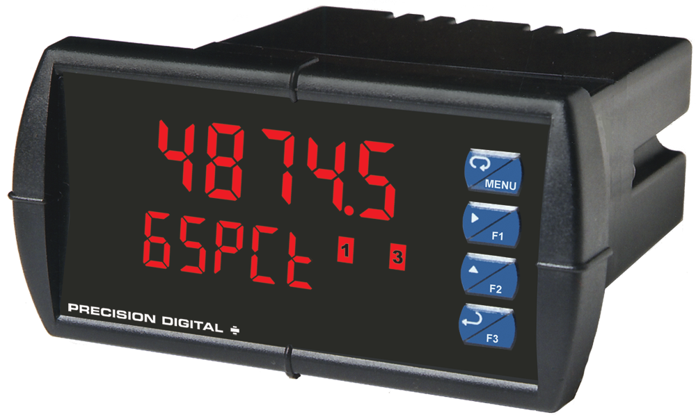
Bright & Optional Super-Bright Display
The standard ProVu’s display is bright enough for most applications, including moderate sun exposure. However, for direct sunlight exposure the ProVu is available with super-bright LEDs that make it possible to read the ProVu even in direct sunlight. Both versions of the ProVu have eight levels of adjustable intensity.
Rounding Feature for Even Steadier Display
The rounding feature is used to give the user a steadier display with fluctuating signals. It causes the display to round to the nearest value according to the rounding value selected (1, 2, 5, 10, 20, 50, or 100).
For example, with a rounding value of 10, and an input of 12346, the display would indicate 12350.
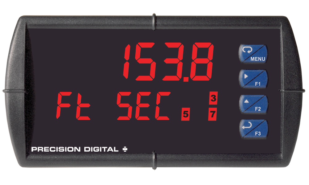
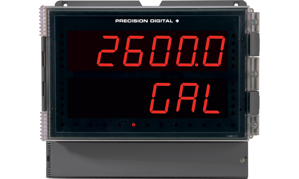
Dual-Scale Display Feature
The ProVu PD6000 has a rather unique, and very flexible dual-scale capability. This is of particular value in level applications where a second scaled display can represent the measured input in a different form (i.e. gallons & height). Both displays are independently scaled and are based on the 4-20 mA input signal. Beyond level, this function has been used for pressure & force, current & power, feet & meters, GPM & CFM, and more.
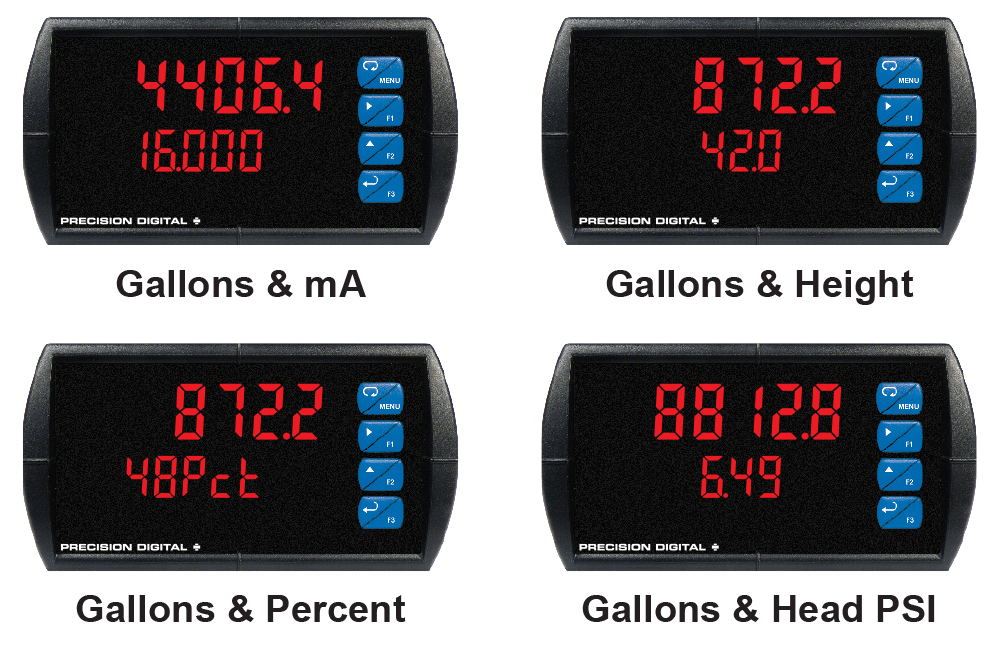
MeterView Pro can be used to program the ProVu to display the input in two different scales:

Toggling Between Reading & Units with Tag
The ProVu can also be programmed so the upper line toggles between the reading and units and the lower line displays a tag. For instance, the upper line toggles between 9500 and Gal and the lower line displays Tank 1.

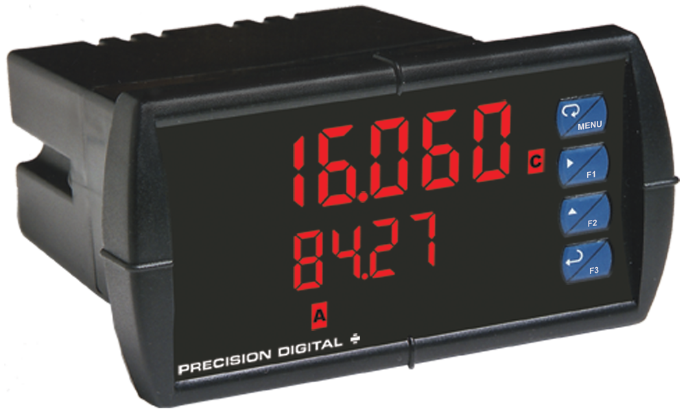
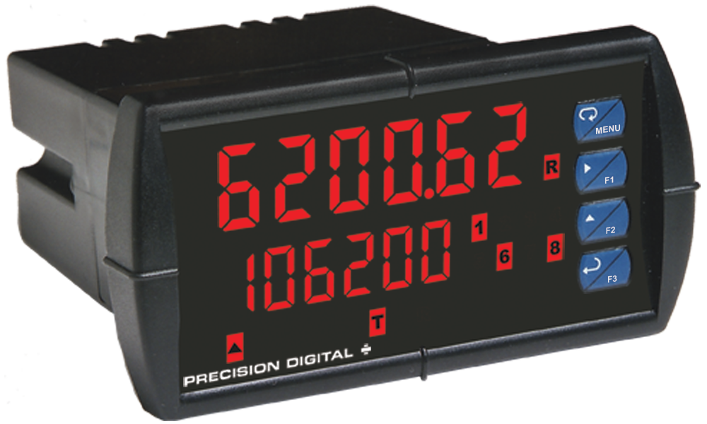
Other Uses for Lower Line
The lower line can also be used to indicate units, a tag, or even a setpoint as the following pictures illustrate:
Reduce Sun Glare On Your Panel Meter Display!

New PDA18DINSH Sun Hood
The PDA18DINSH Sun Hood improves the readability of 1/8 DIN digital panel meters when they are mounted in direct sunlight by shading the instrument from the sun.
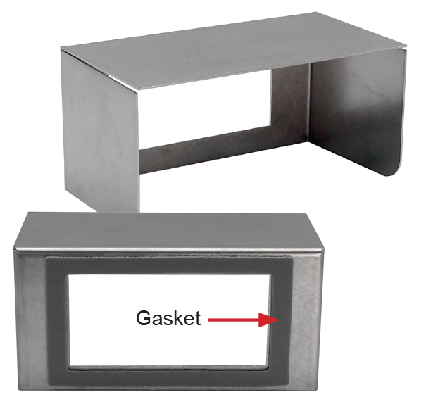
The Sun Hood is made from 18 gauge 316 stainless steel and mounts between the 1/8 DIN digital panel meter and the panel. In addition, a gasket is provided that installs between the Sun Hood and the panel to provide a NEMA 4X seal to the panel. The whole assembly is held in place by the panel meter’s mounting brackets.
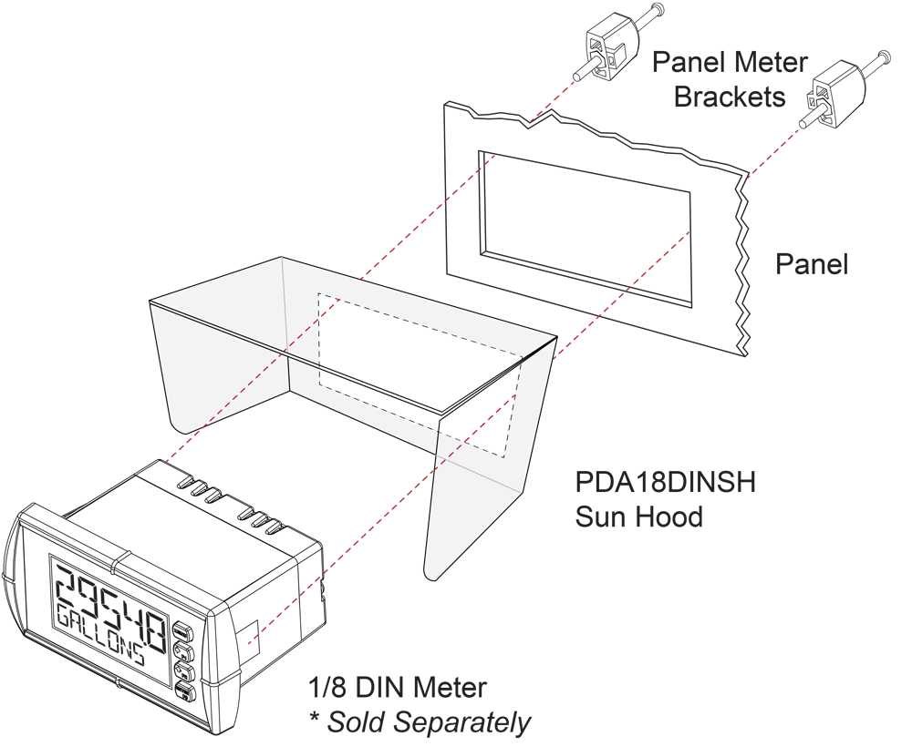
- Provides Shade for 1/8 DIN Digital Panel Meters
- Made from 18 Gauge 316 Stainless Steel
- Easy Mounting Requires No Drilled Holes in the Panel
- Includes Gasket to Maintain NEMA 4X Seal
4-20 mA Output & Relays
Isolated 4-20 mA Analog Output
The isolated analog retransmission signal can be configured to represent the process variable (PV), maximum (peak) value, minimum (valley) value, the value for any of the eight relay set points, or Modbus input. While the output is nominally 4-20 mA, the signal will accurately accommodate under- and over-ranges from 1 to 23 mA.
The 4-20 mA output can be reversed scaled such that 4 mA represents the high value and 20 mA represents the low value. For instance, a 4-20 mA output signal could be generated as the meter went from 100.0 to 0.0.
For applications where the input was linearized by the ProVu, the 4-20 mA output will represent that linearized value.
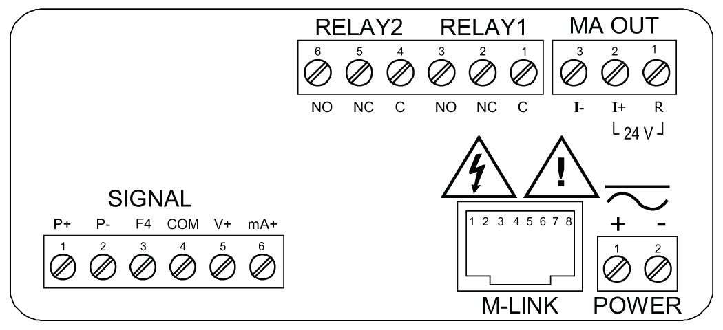
Connections
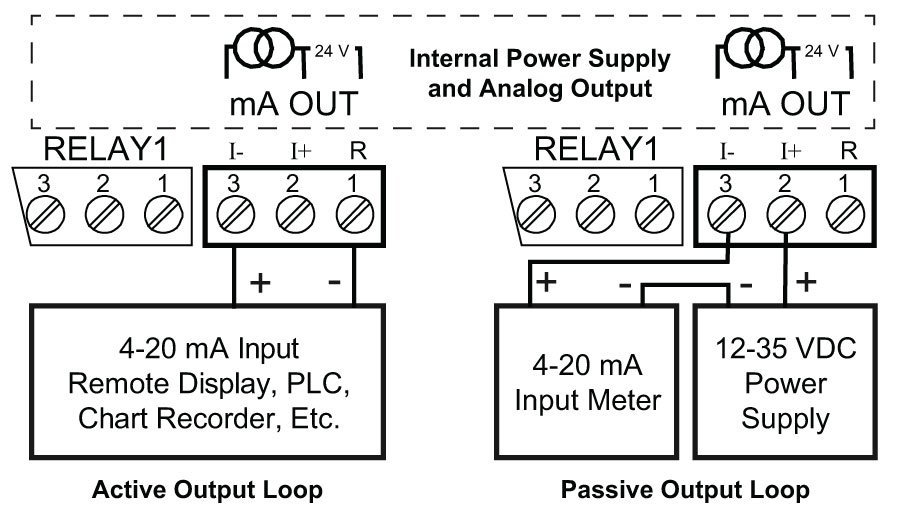
The ProVu can provide 40 mA at 24 VDC to power the 4-20 mA output signal or an external power supply can be used:
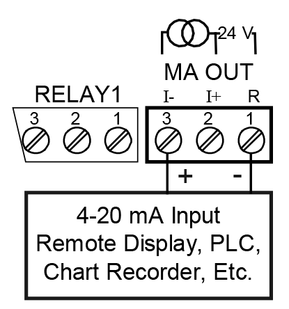
4-20 mA Output Powered by PD6000
4-20 mA Output Powered by External Power Supply
The internal 24 VDC power supply powering the analog output may be used to power other devices, if the analog output is not used. The I+ terminal is the +24 V and the R terminal is the return.
The 4-20 mA analog output can be scaled to provide a 4-20 mA signal for any display range selected. No equipment is needed to scale the analog output; simply program the display values to the corresponding mA output signal. The Analog Output menu is used to program the 4-20 mA output based on display values.

When a meter is programmed as shown to the left, the output will be 4.00 mA when the display reads 0.0 and the output will be 20.00 mA when the display reads 150.0.

The meter can be set up for reverse scaling as shown below: the output will be 4.00 mA when the display reads 150000 and the output will be 20.00 mA when the display reads 0.
Source: Source for generating the 4-20 mA output (e.g. PV)Overrange: Analog output value with display in overrange conditionUnderrange: Analog output value with display in underrange conditionBreak: Analog output value when loop break is detectedMax: Maximum analog output value allowed regardless of inputMin: Minimum analog output value allowed regardless of input
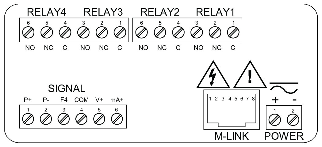
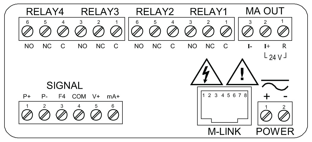
Relays for Alarm & Control Applications
Adding relays to the ProVu meter turns it into a sophisticated alarm device as well as a powerful, yet simple, alternative to a more complicated PLC system for control applications. One such application would be pump control using the ProVu’s relays in pump alternation mode. The ProVu can be equipped with up to four 3 A Form C (SPDT) internal relays and an additional four more 3 A Form A (SPST) external relays. Relays are highly user-configurable as the following screen shot from MeterView Pro indicates:

*Values are intended to show programming choices. They are not intended to represent an actual application.
- Program Set and Reset Points (HI / LO Alarms)
- Reset the Relays (Action in MV)
- Time Delay (On and Off)
- Relays Auto Initialization
- Signal Loss or Loop Break Relay Operation
- User Selectable Fail-Safe Operation
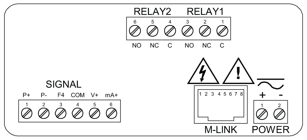
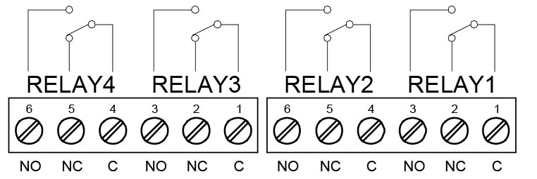
Relay connections are made to a six-terminal connector labeled RELAY1 and RELAY2.

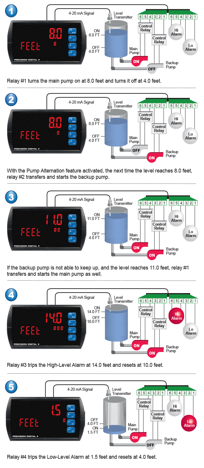
Multi-Pump Alternation
The ProVu can be used as a pump controller when combined with a continuous level transmitter. The most common pump control application is shown below: controlling and alternating two pumps and providing high and low-level alarms. The light / horn accessory can be added to provide visual and audible alarm indication.
Signal Input Conditioning
There are many applications in the industrial world that can’t be satisfied with simple, two-point linear scaling so the ProVu has advanced linearization capabilities to handle applications like round horizontal tank volume measurement, open channel flow, DP flow, and others. And all of these capabilities are easily programmed using MeterView Pro programming software.
32-Point Linearization
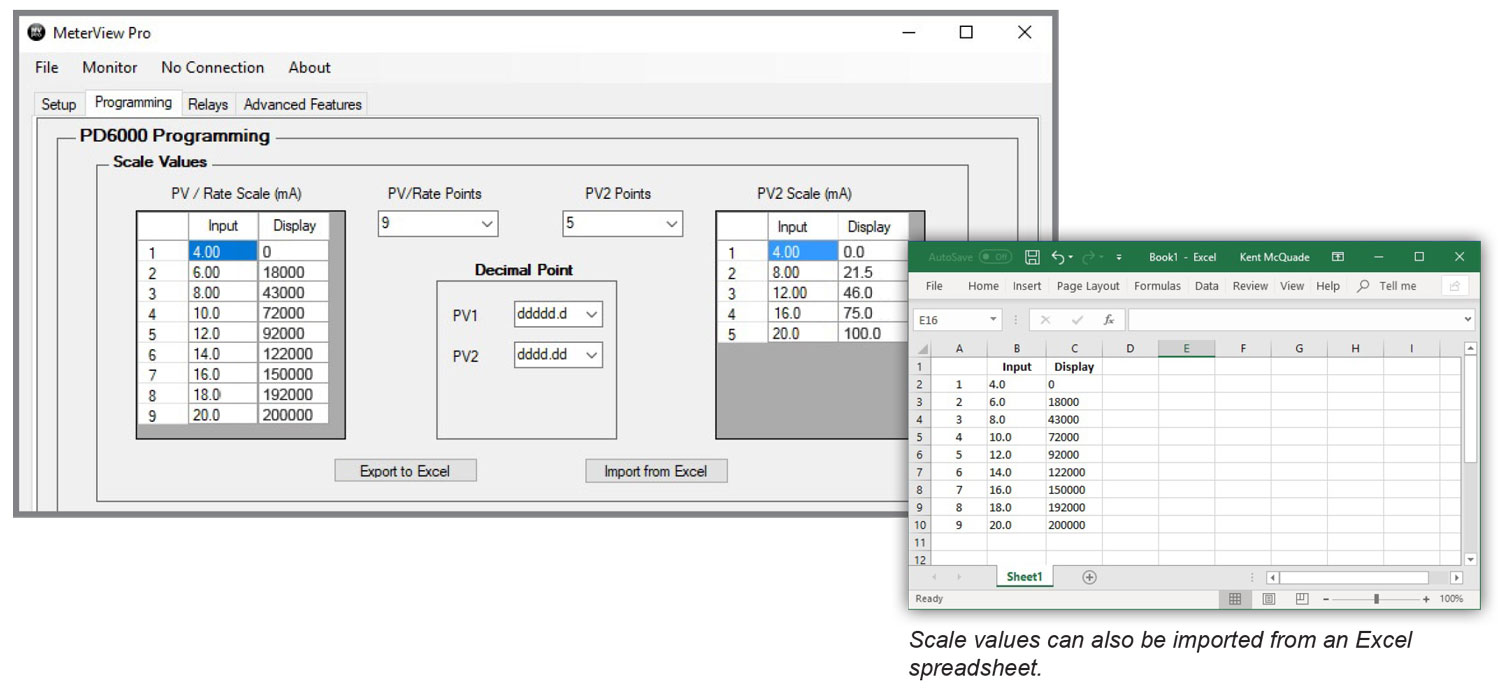
The most common way to linearize a non-linear signal is to break it up into smaller ranges that are more linear than the overall range. The ProVu is available with up to 32 points of linearization and if dual scale feature is used, the second PV can have up to eight points of linearization. The linearization data can be imported from an Excel spreadsheet or can be exported from MeterView Pro to an Excel spreadsheet. The following screen shot from MeterView Pro shows PV1 with 9 points of linearization and PV 2 with 5 points of linearization:
Specialized Linearization Functions
In addition to the generic 32- and 8-point linearization functions, the ProVu is also available with specialized functions for round horizontal tanks, open channel flow, and DP flow.
Round Horizontal Tank
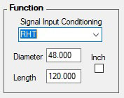
The user enters the diameter and length of a flat-ended round horizontal tank resulting in a display of volume.
Programmable Exponent
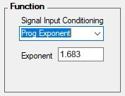
The input is raised to an exponent progrmmable by the user resulting in a display of open channel flow rate.
Square Root Extraction
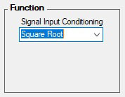
The square root of the input is taken resulting in a display of flow rate.
Round Horizontal Tank Volume Linearizer
In this application, a level sensor is measuring the height in the round horizontal tank and the ProVu is converting that signal to volume using the RHT function. All the user has to do is input the diameter and length of the tank and the meter converts the signal to volume.
Open Channel Flow Rate Indication
In this application, a level sensor is measuring the height in a weir and the ProVu is converting that signal to flow rate using the programmable exponent function. All the user has to do is input the corresponding exponent for their weir and the meter will convert the signal to flow.
DP Flow via Square Root Extraction
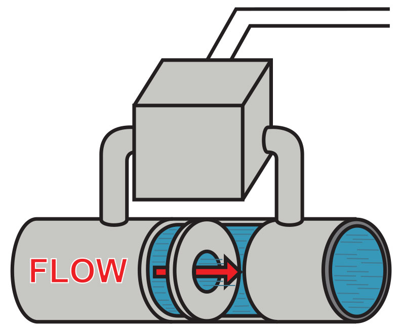
In this application, the PD6000 is displaying flow rate by extracting the square root from the 4-20 mA signal from a differential pressure transmitter. The user selectable low-flow cutoff feature gives a reading of zero when the flow rate drops below a user selectable value.
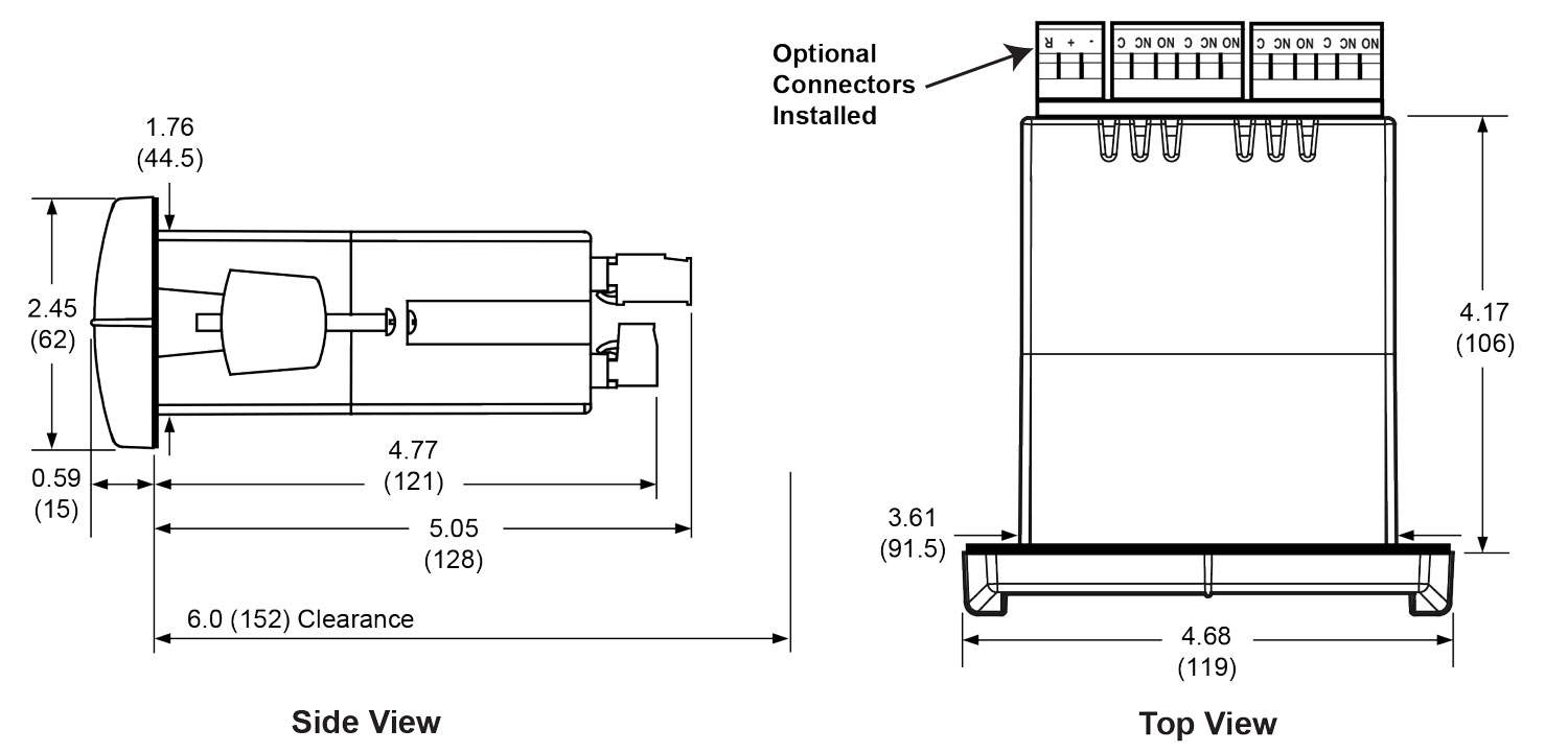
Physical Features
The ProVu is designed for ease-of-use in industrial applications. Considerations include a NEMA 4X front panel, wide operating temperature range, removable screw terminal connectors, snap in place mounting brackets, forgiving panel cutout requirement, and UL Listing for electrical safety. All of these features are backed by a 3-year warranty.

Wide Operating Temperature Range
The ProVu can operate from -40 to 65°C (-40 to 150°F) meaning it can be installed in a wide variety of indoor and outdoor industrial applications. And over this range, the ProVu will drift no more than 0.005% of calibrated span/°C max from 0 to 65°C ambient and 0.01% of calibrated span/°C max from -40 to 0°C ambient.
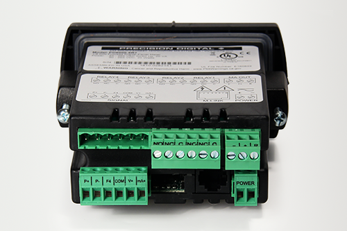
Removable Screw Terminal Connectors
Industrial applications require screw terminal connections for easy field wiring and the ProVu goes one step further in convenience by making them removable also.
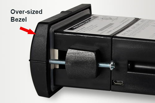
Forgiving Panel Cutout Requirement
The ProVu’s bezel has been oversized to allow for not perfectly executed panel cutouts where NEMA 4X seal is not required.
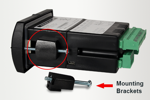
Secured-in-Place Rugged Mounting Brackets
If you’re installing the Trident outdoors in the hot or cold weather, the last thing you want to do is fumble around with mounting brackets that don’t stay in place. The Trident's mounting brackets can be easily secured into place and then screwed down to the panel. These brackets are rugged so they can be tightened to the panel to provide a solid NEMA 4X seal.
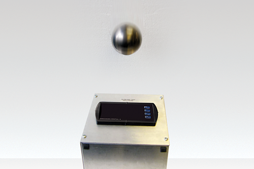
Type 4X / NEMA 4X Front Panel
Not only does the Trident’s front panel UL Type 4X approval indicate it is waterproof, but it also indicates it is rugged. Part of the UL Type 4X test is to drop a 2-inch solid stainless steel ball from 8 feet on top of the meter’s faceplate.
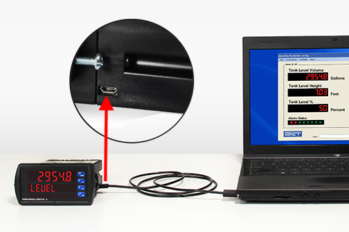
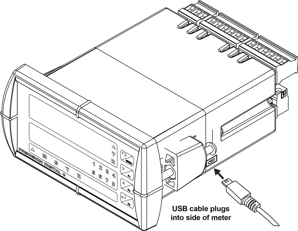
USB Port for Free MeterView Pro Software
Easily connect the ProVu process meter to a PC with via the USB port for MeterView Pro programming software.
Operational Features
There are three ways the user can interact with the ProVu to perform a variety of useful functions:
1. Three Front Panel Function Keys
The default settings for the function keys are:

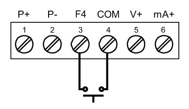
2. F4 On-Board Digital Input
The PD6000 includes a digital input as standard. This digital input can operate with the tare, reset tare, or interlock relays feature, force relays on from a signal from a PLC or relay on other equipment, and much more. This is ideal for installations where the meter is inaccessible behind a cover, or where an additional function key is needed for customized operation.
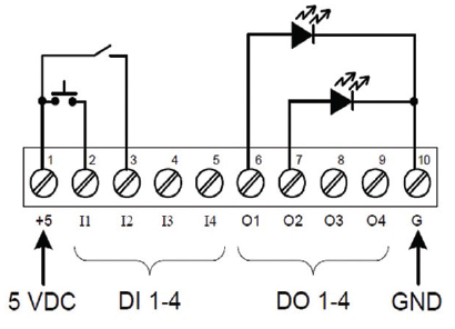
For instance, these button contacts can be used to program the meter and to remotely acknowledge/reset the relays:
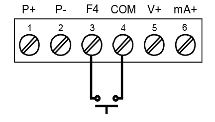
The F4 terminal is particularly useful for wiring up a remote switch to reset the relays as shown here:
3. Optional 4 Digital Input/Output Module PDA1044
With these three methods, the ProVu can be programmed to trigger certain events (i.e acknowledge relays, reset max and/or min, disable/enable output relays, or hold current relay states), provide direct menu access points and more.
Plastic Control Stations For The ProVu PD6000
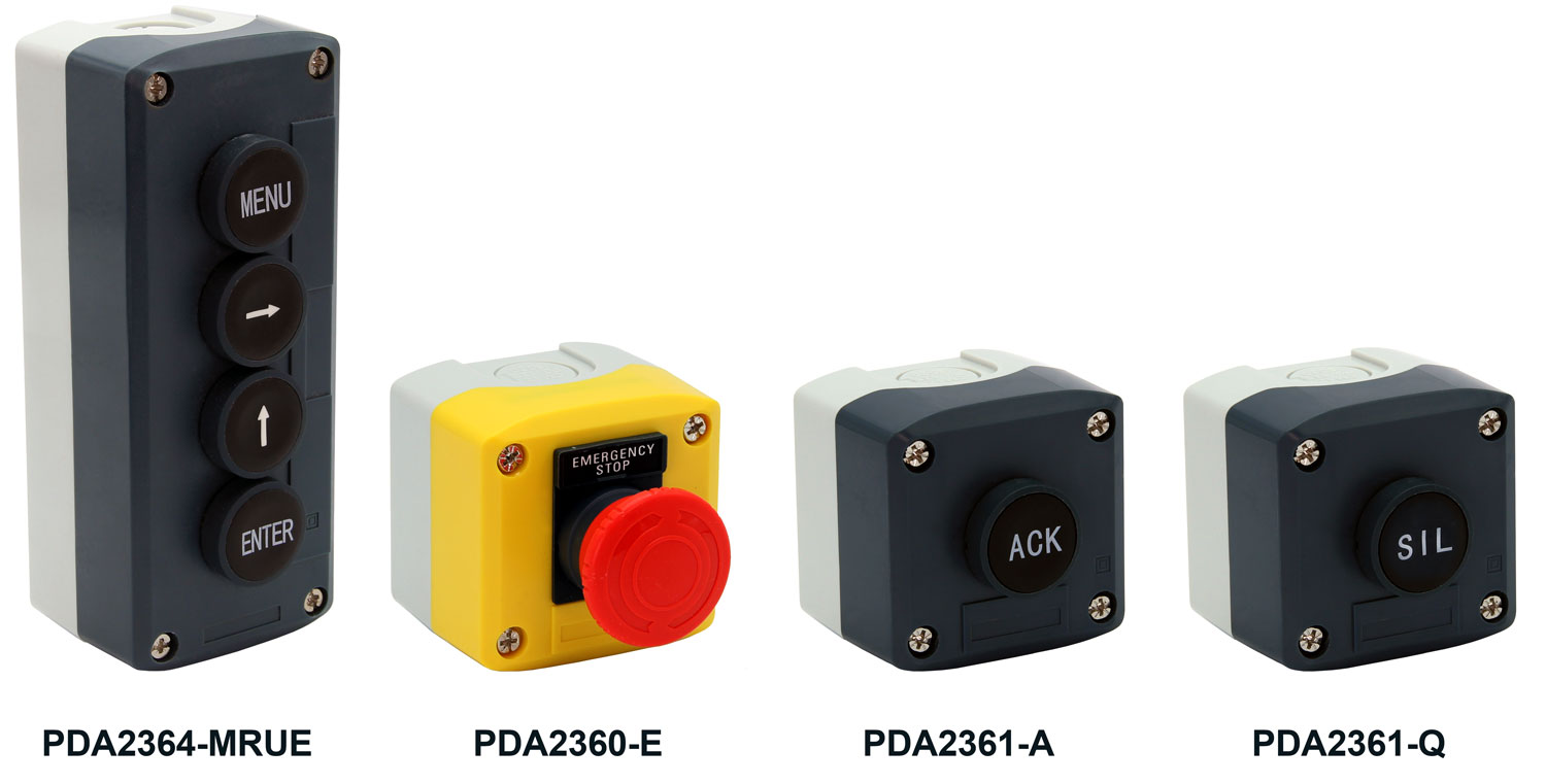
The PDA2360 series of plastic control stations provide a convenient way to remotely control devices such as Precision Digital’s ProVu PD6000. The PDA2364-MRUE four-position control station mimics the ProVu’s four front panel buttons: Menu, Right Arrow, Up Arrow, and Enter. The PDA2360-E is an emergency stop button, the PDA2361-A is used to acknowledge an alarm, and the PDA2361-Q is to silence an alarm.
- Complete Pre-Assembled Stations
- Normally Open (NO) Spring Return Plastic Bezel Pushbuttons
- Trigger Action Turn to Release Pushbutton (PDA2360-E only)
- IP65 / NEMA 4, 4X and 13 Rated
- Four-Position Control Station for Remote Operation of ProVu Buttons
- Wall Mountable
| PDA2360 Series Control Stations | |
| Model | Description |
| PDA2360-E | Emergency Stop Button |
| PDA2361-A | 1 Black Ack Button |
| PDA2361-Q | 1 Black Silence Button |
| PDA2364-MRUE | 4 Black Buttons: Menu, Right, Up, Enter |
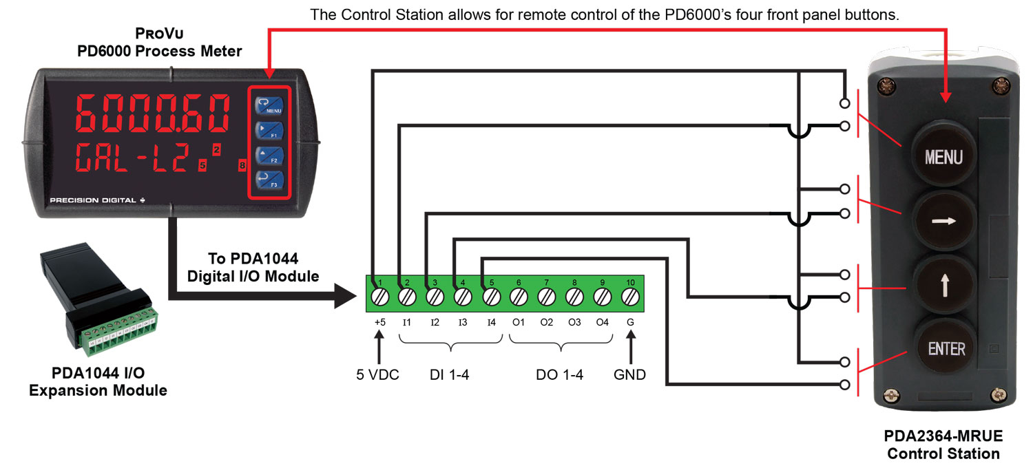
Four-Position Control Station for Remote Operation of ProVu Buttons
The ProVu PD6000's four programming and operations buttons can be remotely controlled by using the PDA2364-MRUE 4-button control station accessory as shown in the diagram below.
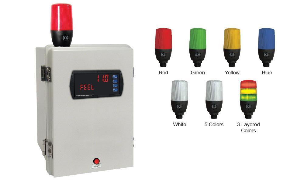
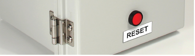
Light/Horn & Button Mounted to Enclosure
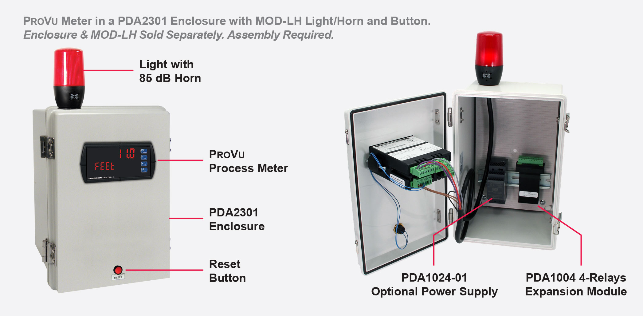
Precision Digital offers a wide variety of NEMA 4 and NEMA 4X enclosures that can be equipped with MOD-LH Light/Horn and Button. When MOD-LH is ordered, the accompanying enclosure on the order comes with the holes pre-drilled for the Light/Horn and the Button and the user performs the mounting and wiring. Meter and enclosure are sold separately. The Light/Horn and the Button can also be ordered as separate items and the user performs all holedrilling, mounting and wiring as desired.
The light and horn can be controlled independently of each other via separate relays on the Trident X2 meter; and since the meter's relays can be reset in a variety of ways, there are several ways the Light/Horn option can operate. For instance, the horn can be programmed to silence at any time via the Button or front panel button on the Trident X2, and light to reset automatically when the alarm clears as the following table illustrates:
| Relay # | Connected to | Default Reset Mode |
| 1 | Flashing Light(1) | Auto reset |
| 2 | Horn | Silence with Button at any time |
- Light can be wired to flash or stay steady on
- See manual or data sheet for additional ways the relays can be programmed
Note: The Light / Horn accessory is powered from the 200 mA transmitter power supply; so when it is installed, there is less power available for the transmitter. See MOD-LH Light / Horn, Transmitter Power Supply specification in the manual or data sheet for details.
Light/Horn Dimensions
Units: Inches (mm)