PDW Manager software is an easy-to-use tool for programming the PDW30 or PDW90 wireless products. All that's required is a PC with a USB connection, and you'll be up and running in no time. Use of PDW Manager is required for programming the PDW90 base station or advanced settings, such as wireless encryption, and analog signal calibration. Download PDW Manager here.
Programming The PDW30 Field Units
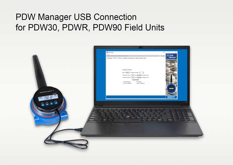
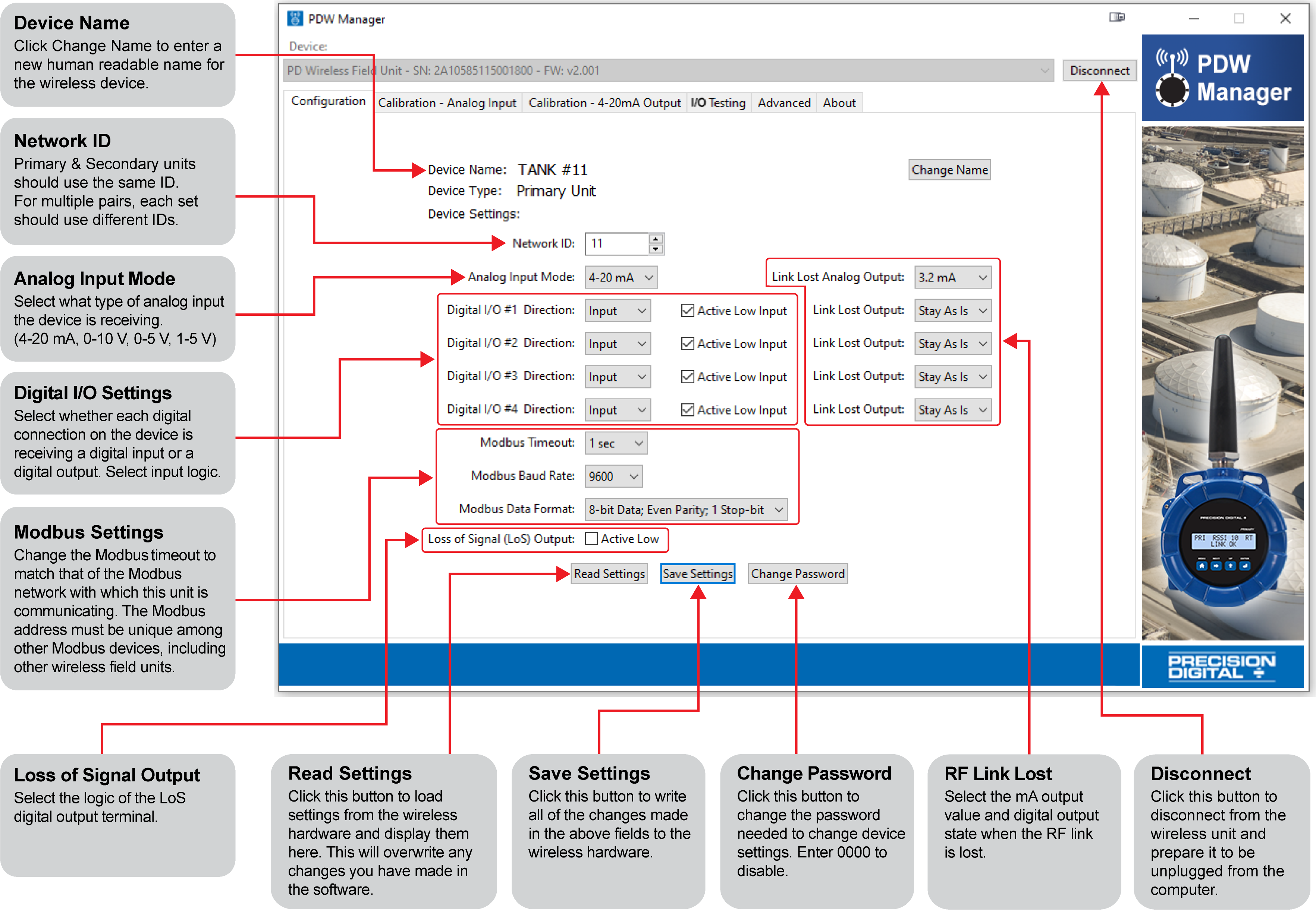
PDW Manager allows you to program the PDW30 wireless units from a PC with a USB connection. Units connect to a PC via the micro USB connection on the side of the electronics module, underneath the enclosure cover. Use of PDW Manager is required for programming advanced settings such as digital I/O logic (high or low), loss of signal (LoS) digital output state or analog output value, wireless encryption, and analog signal calibration.
Once the software is running, power the unit using a 9-30 VDC power supply and connect the device to the PC using the provided USB cable.

The PC will automatically install the appropriate device drivers. Once this has completed, the device will appear in the Device list at the top of the PDW Manager window. Click Connect.
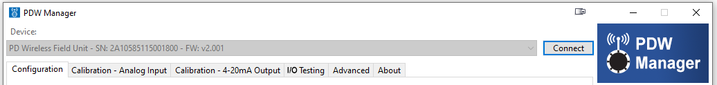
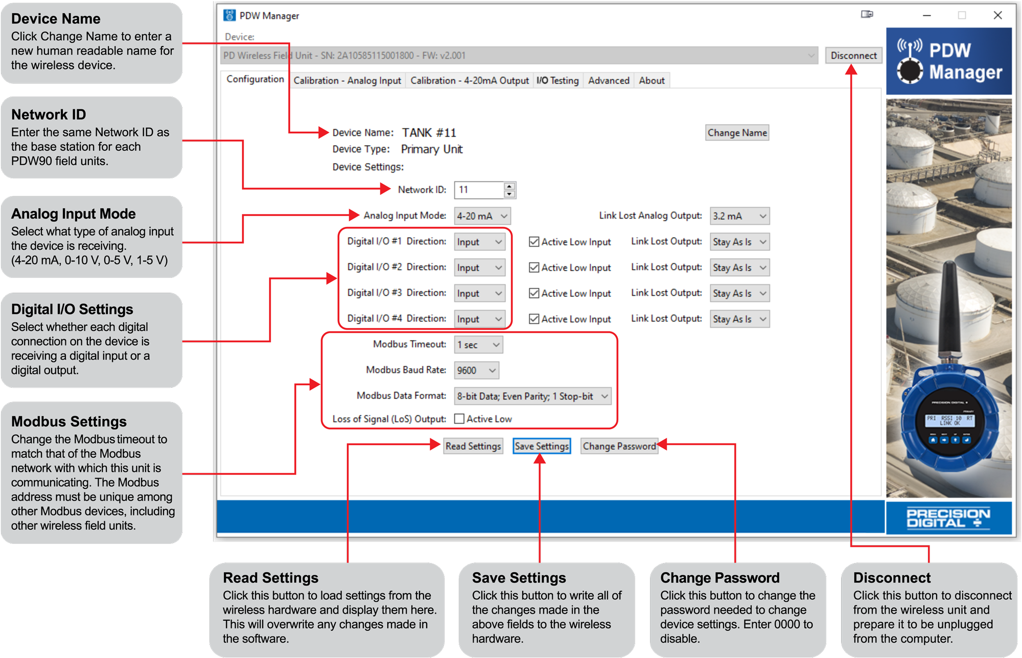
The menu options displayed will vary depending on what type of unit is connected. The PDW30 primary unit will have more options than the secondary unit. The image below shows the available options on the Configuration tab while the primary unit is connected.
Analog Input & Output Calibration
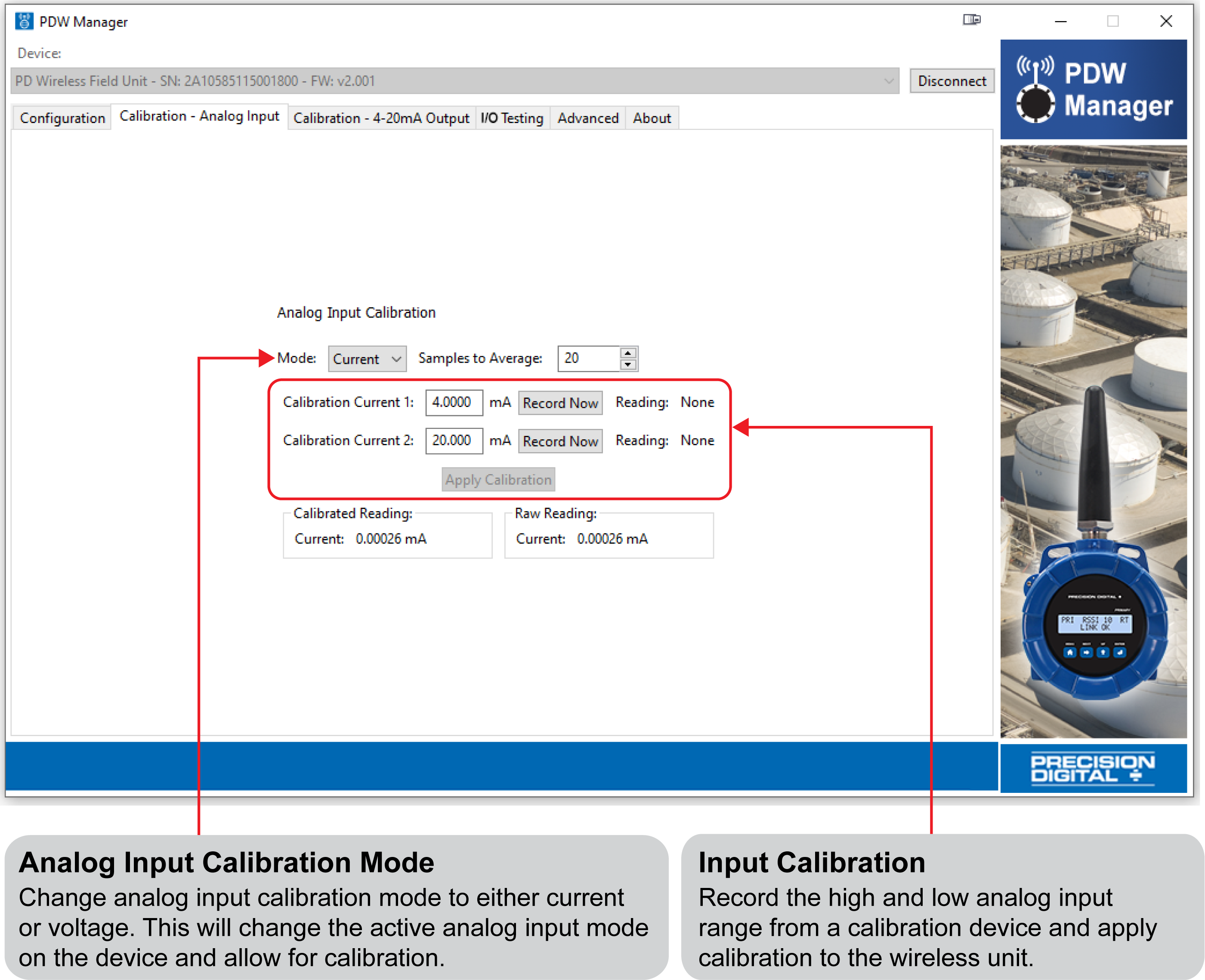
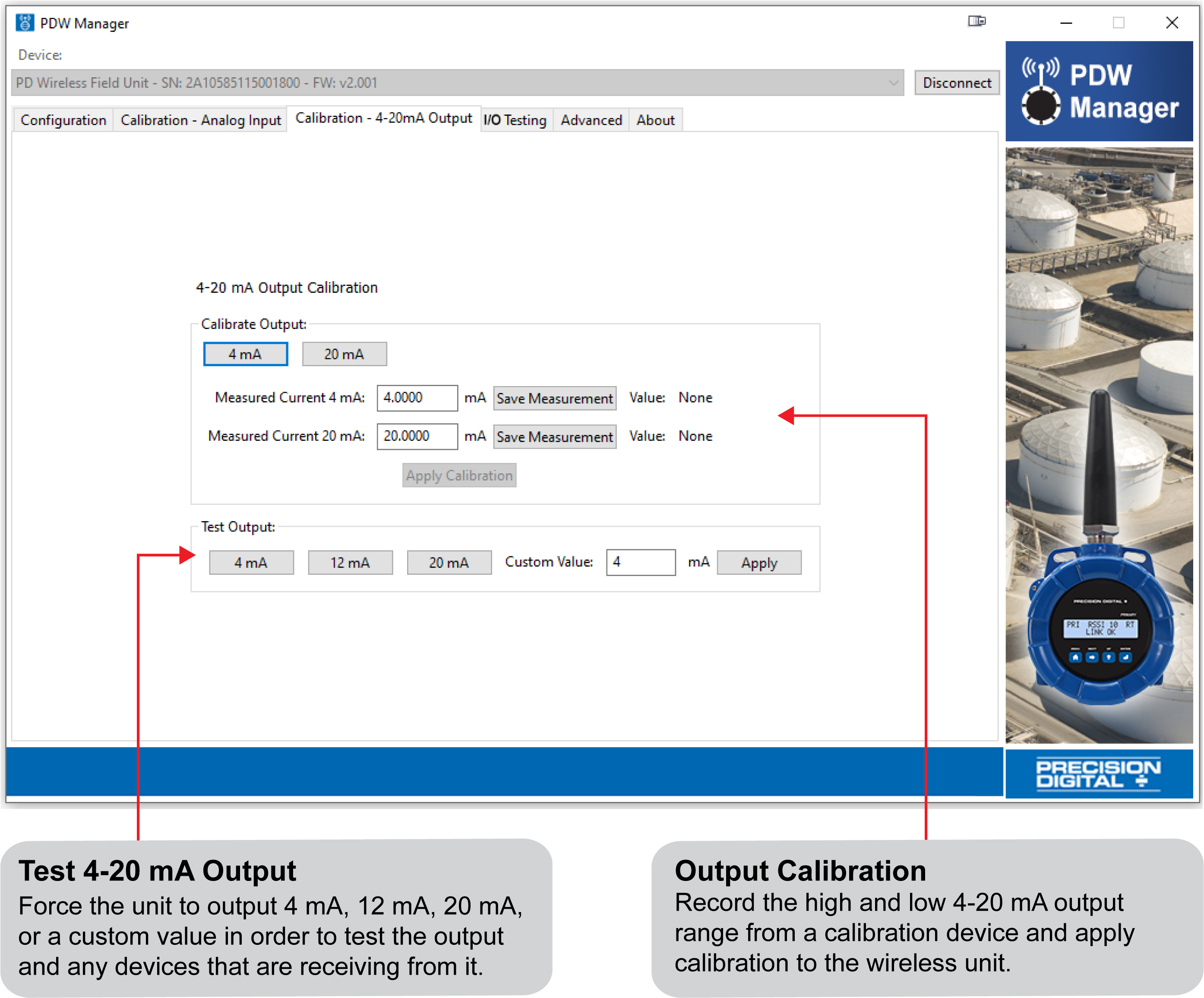
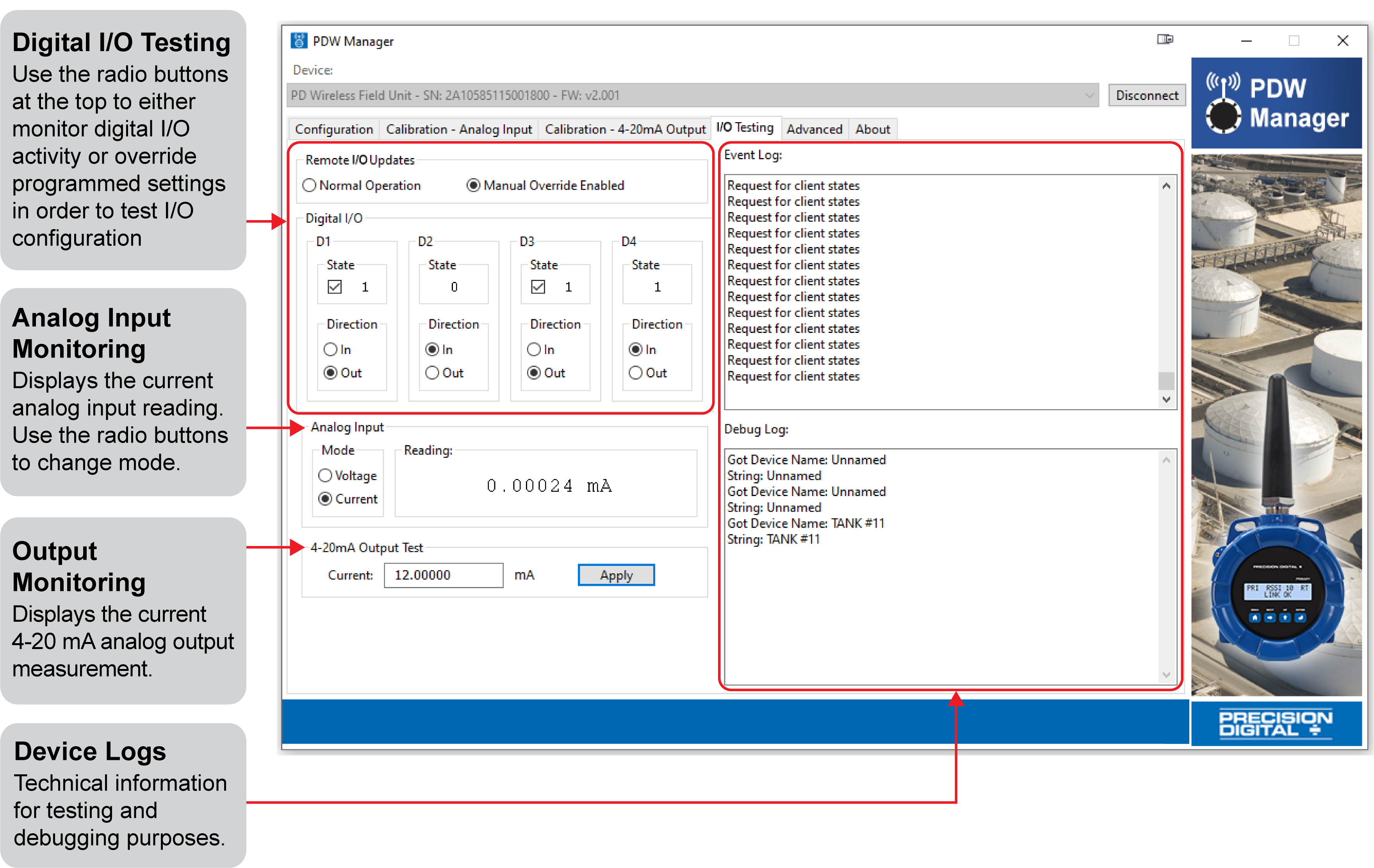
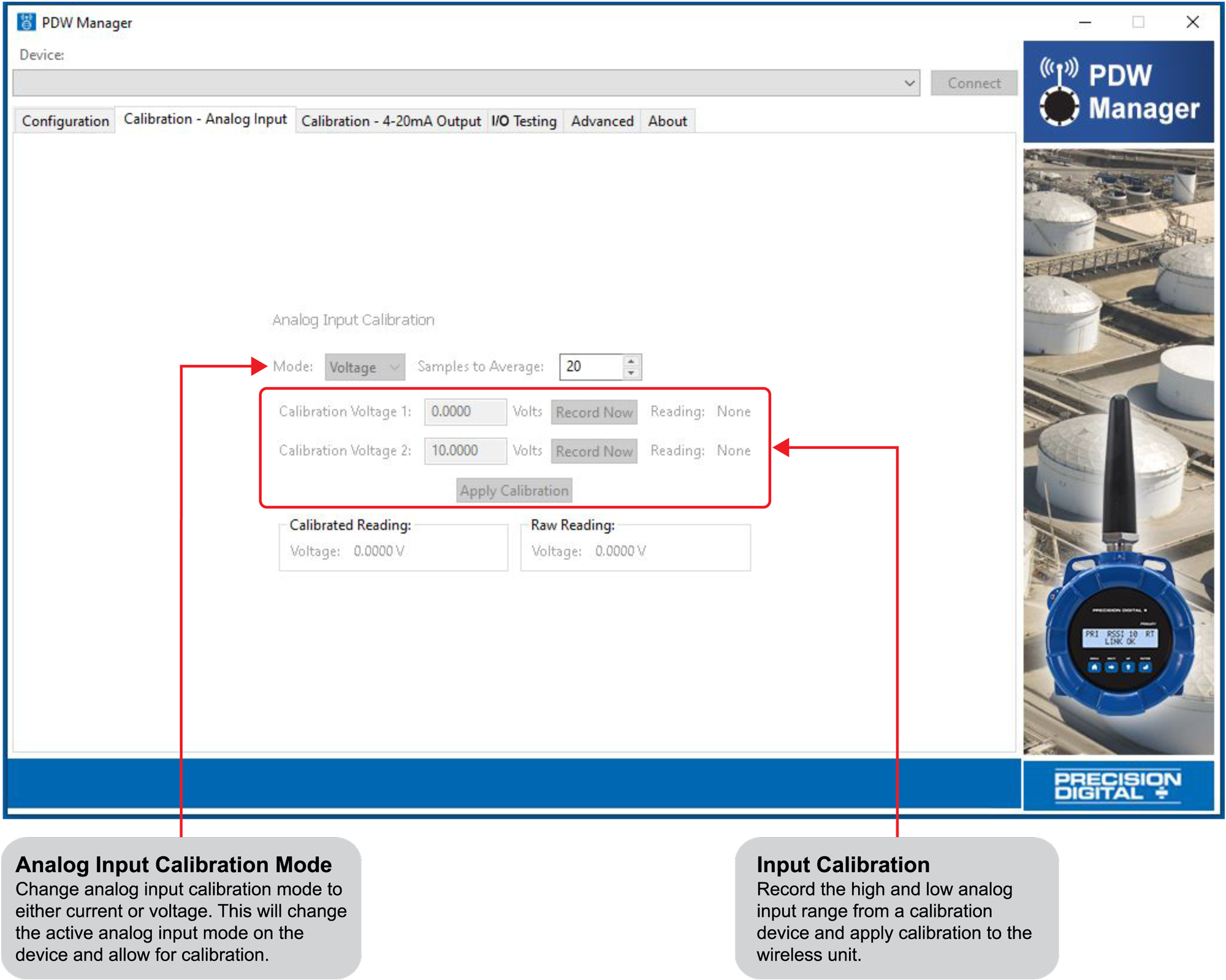
The devices’ analog inputs and outputs can be calibrated using the Calibration tabs. The I/O Testing tab allows you to perform diagnostics and testing on the units.
Note: The PDW30 units are factory calibrated prior to shipment to read analog input in milliamps and volts depending on the input selection. The calibration equipment is certified to NIST standards.
Calibration - Analog Input
Calibration – 4-20 mA Output
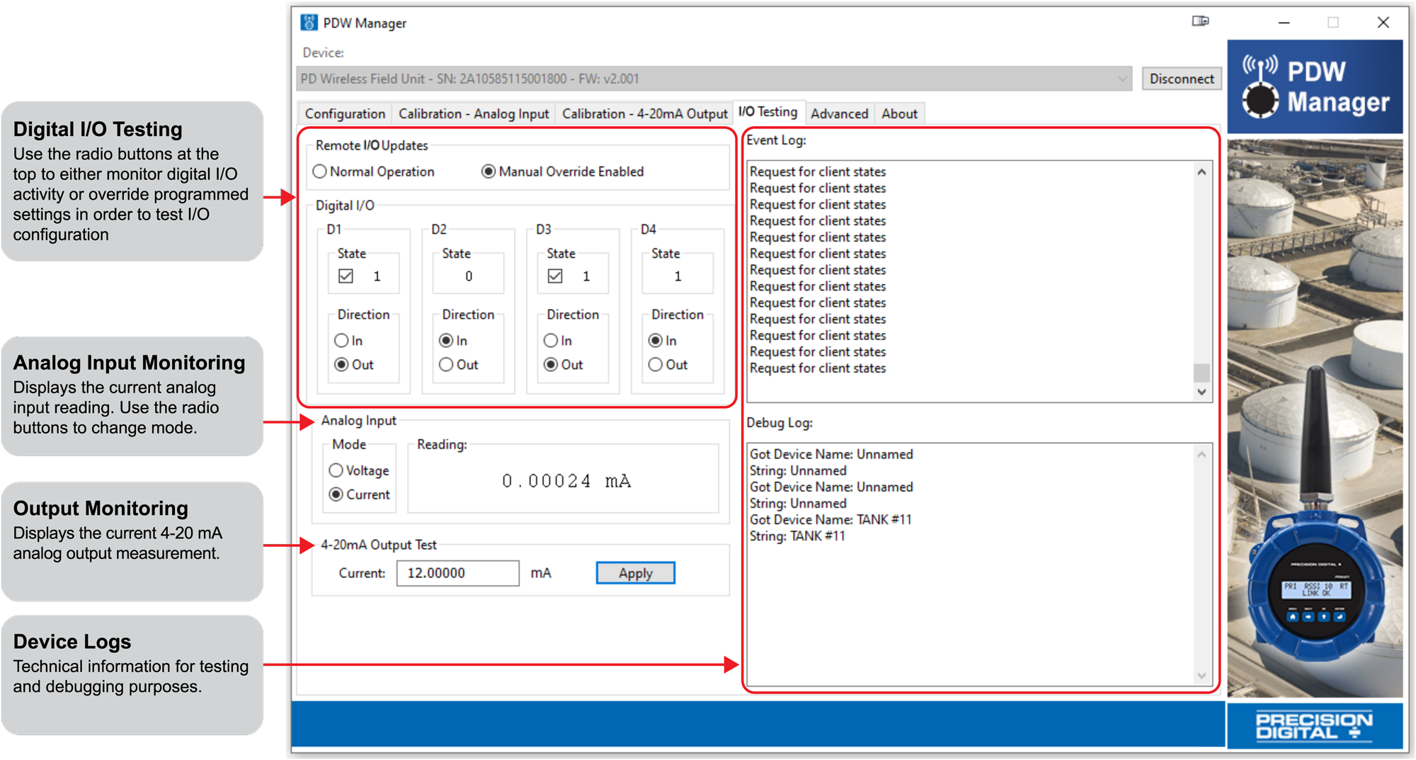
I/O Testing
Networking Settings and Security
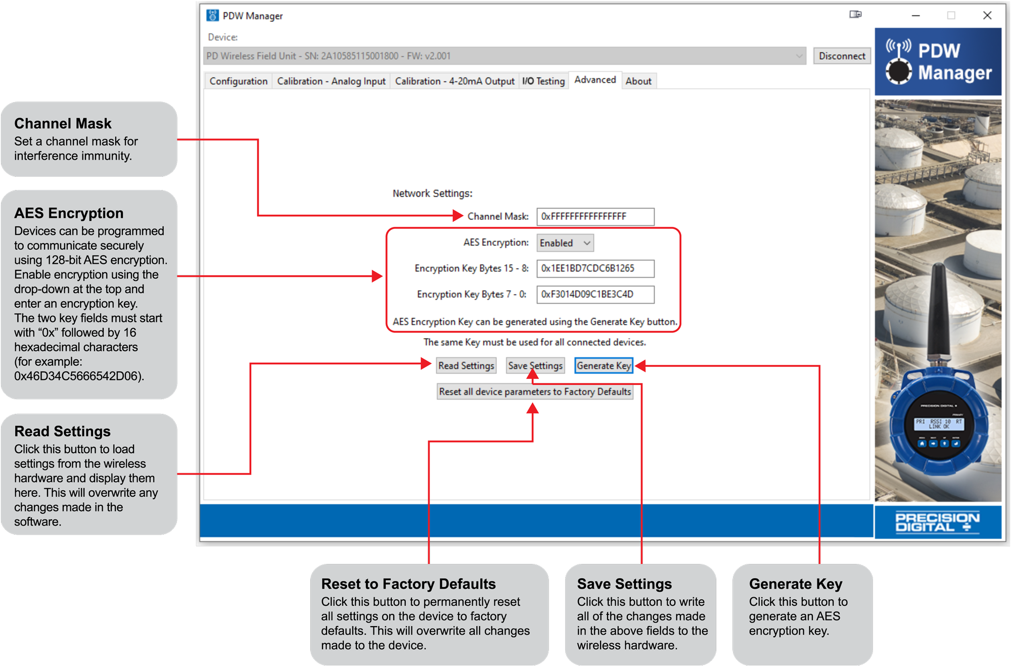
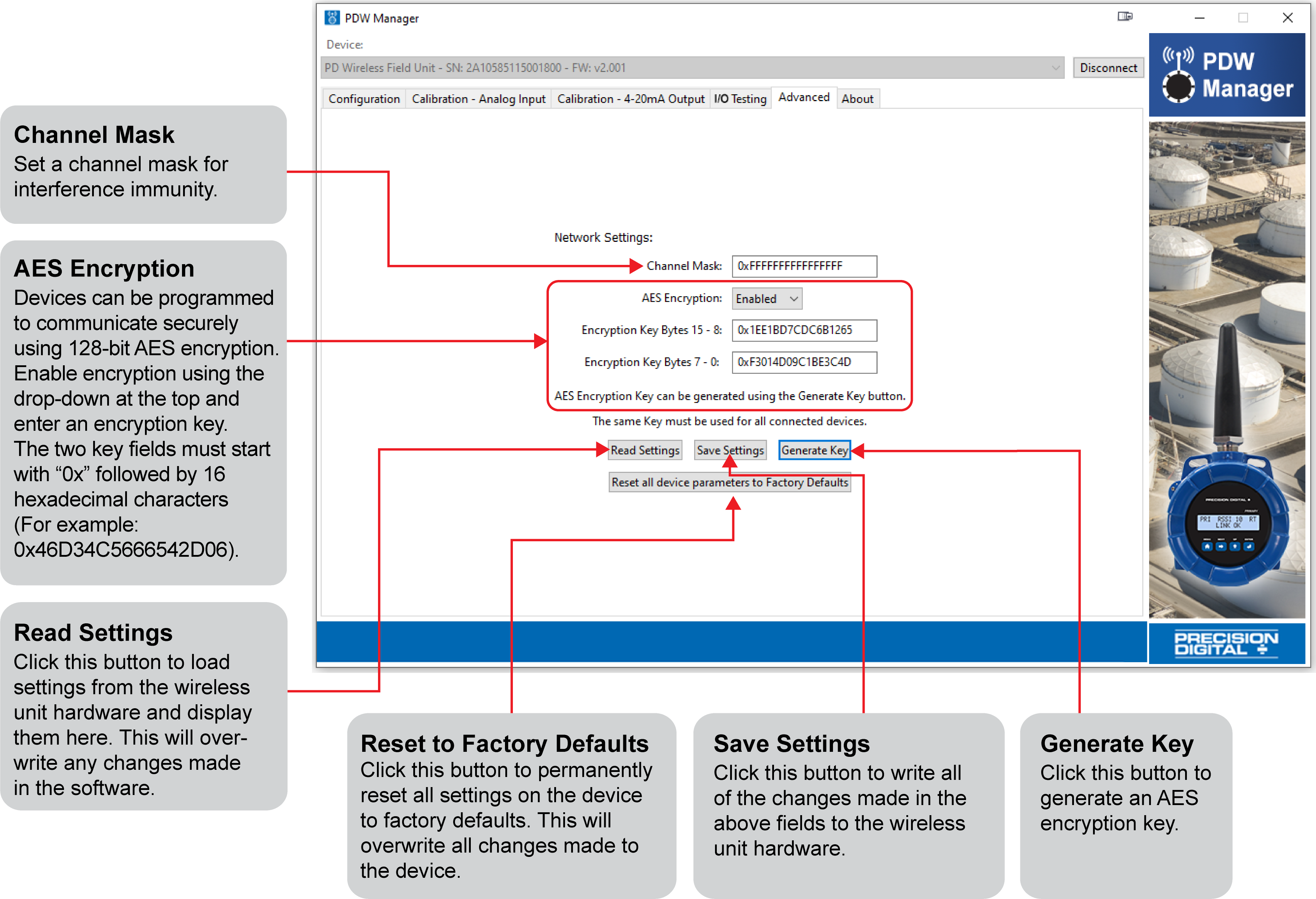
Device communication can be secured by enabling 128-bit AES encryption. A channel mask may also be set for interference immunity. The encryption key and channel mask may be entered on the Advanced tab.
Once the encryption information has been entered, click Save Settings. The wireless devices must share identical encryption keys to communicate, so be sure to enter the same information for the second unit.
Programming The PDW90 Base Station
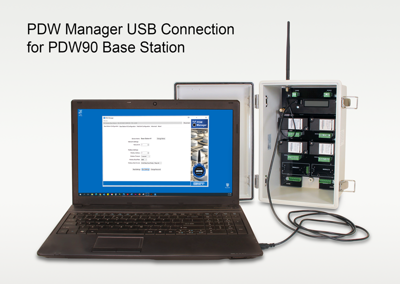
Setup and programming of the base station is done using PDW Manager programming software.
Setup of the wireless field units is done either wirelessly through the base station using PDW Manager programming software, or via direct USB programming with PDW Manager.
Once the software is running, power the unit using a 24 VDC power supply and connect the base station’s micro USB port to a PC using the provided USB cable.
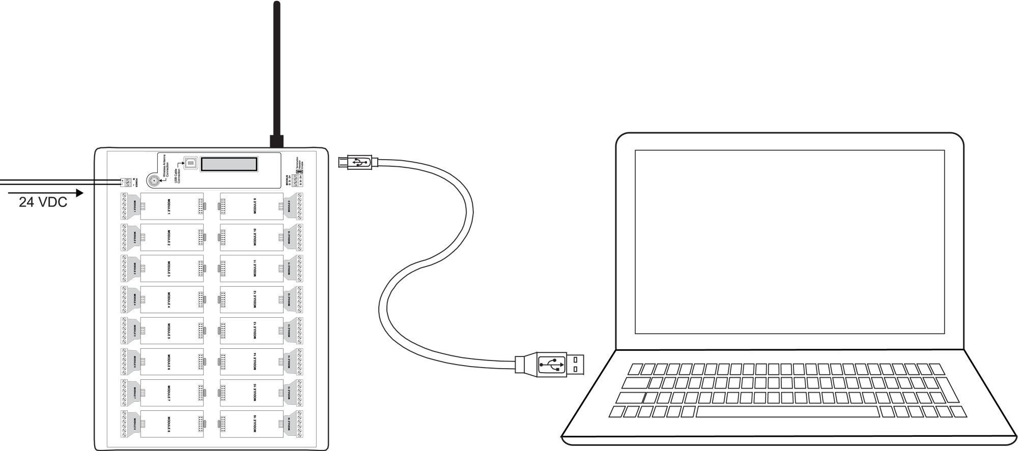
Note: The base station must be powered externally prior to programming via USB
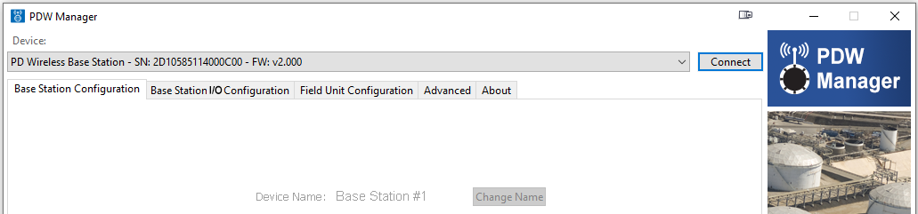
The PC will automatically install the appropriate device drivers. Once this has completed, the device will appear in the Device list at the top of the PDW Manager window. Click Connect.
Connecting Field Units to the Base Station
The first step in the PDW90 programming process is to connect all of the wireless field units to the base station. Con-figuration of the base station is accomplished using the PDW Manager software. The field units may be programmed using PDW Manager, however, because of the limited number of options, it is easier in most cases to use the CapTouch through-glass buttons.
After the base station has been connected to PDW Manager, field units can be connected to it from the Field Unit Configuration tab. Select each unit from the Unassociated Field Units list and click the Add to Client List button.
Field units must have the same network ID and encryption settings as the base station in order to connect. Each field unit must be programmed to have its own unique Modbus address.
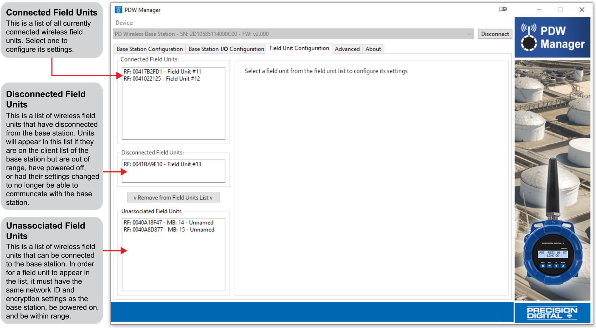
Note: All units must be powered in order to connect them to the base station.
Base Station Configuration
The Base Station Configuration tab is where the base station name, network ID, password, and Modbus settings may be modified. Once the modifications are complete, click the Save Settings button to write the current settings to the device.
If changes have been made that have not been saved, the settings can be loaded from the base station by clicking the Read Settings button.
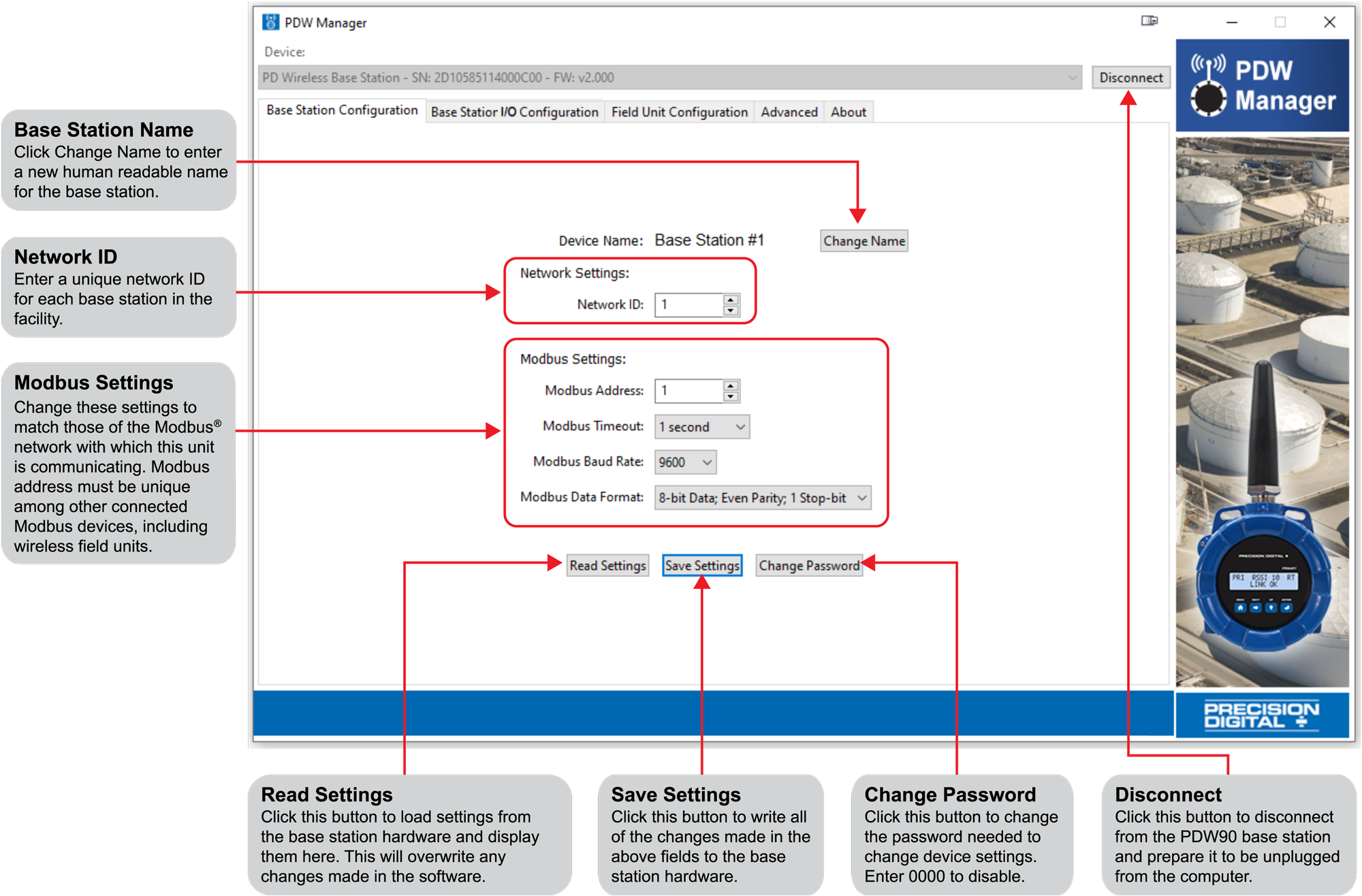
Note: Do not click Save Settings button after changing the password. Click Disconnect to confirm the password has been changed.
Input / Output Base Station Module Configuration
The Base Station I/O Configuration tab is where individual I/O modules connected to the base station are pro-grammed. Click on one of the installed modules in the I/O Modules list to the left of the screen to begin programming that module.
Dual Analog Input Base Station Module
Each Dual Analog Input module has two input channels. Each channel may be independently programmed to accept either a 4-20 mA, 0-10 V, 0-5 V, or 1-5 V analog input. These channels may also be mapped to remote analog outputs or Modbus registers. Once the module’s settings have been modified, click the Save Module Configuration button to save these settings to the base station.
If changes to the module have been made that have not been saved, the settings can be loaded from the base station by clicking the Read Settings from Hardware button. Resetting the selected module to its default settings can be done by clicking the Load Default Settings button.
The Monitoring area at the bottom may be used to view the current analog input reading or manually test analog input operation.
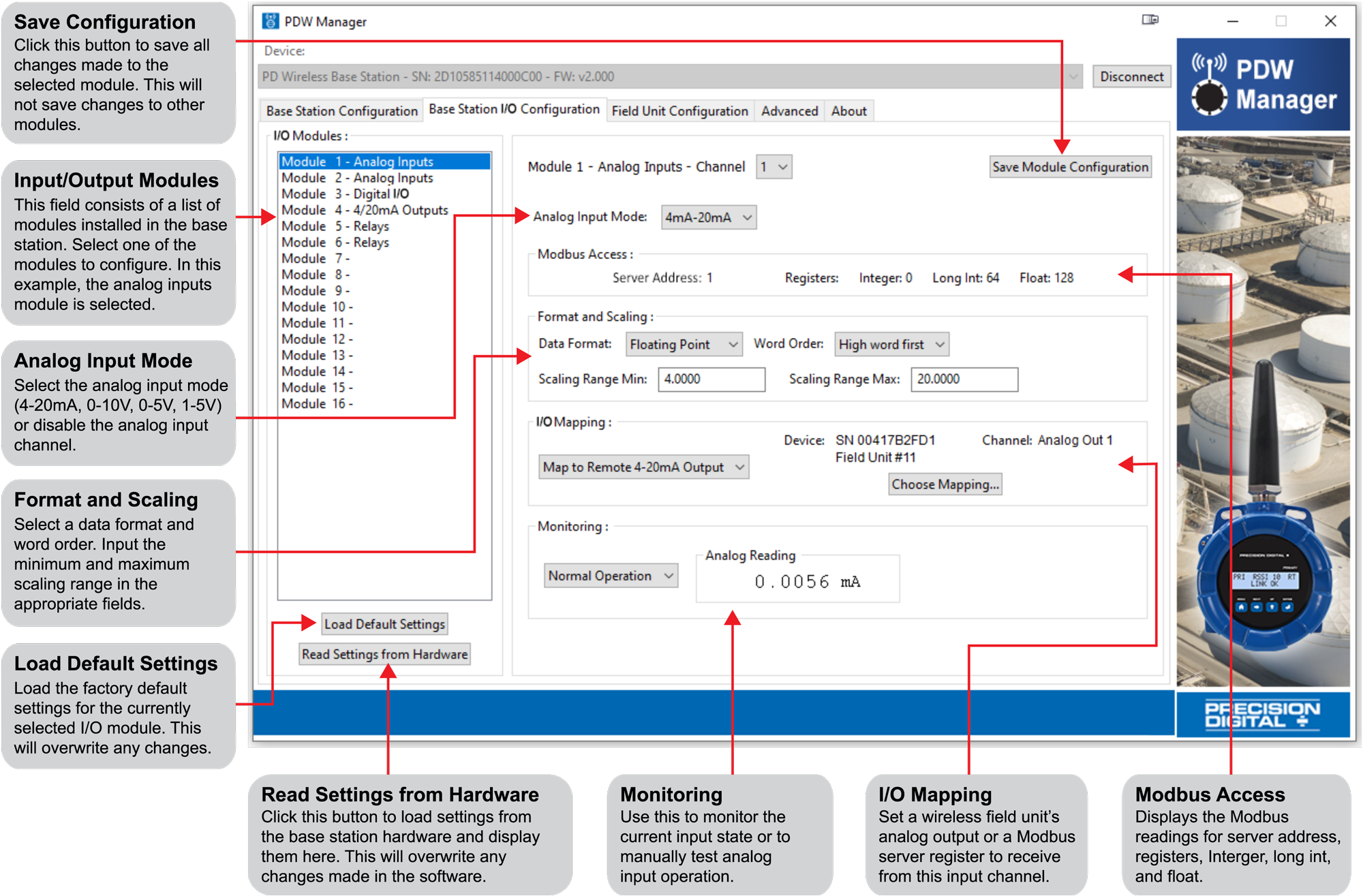
Note: For information about Modbus Access, please see Modbus Register Address vs Modbus Register.
Dual Analog Output Base Station Module
Each Analog Output module has two 4-20 mA output channels. Each channel may be independently programmed and mapped to remote analog inputs or Modbus registers. Once the module’s settings have been modified, click the Save Module Configuration button to save these settings to the base station.
If changes to the module have been made that have not been saved, the settings can be loaded from the base sta-tion by clicking the Read Settings from Hardware button. Resetting the selected module to its default settings can be done by clicking the Load Default Settings button.
The Monitoring area at the bottom may be used to view the current analog input reading or manually test analog input operation.
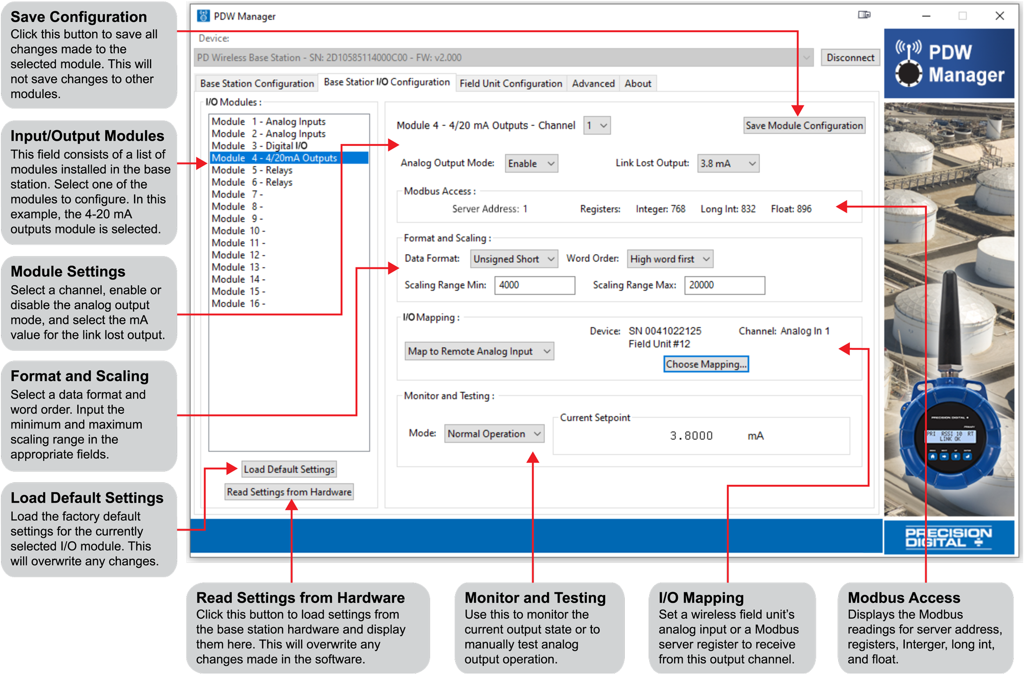
Note: For information about Modbus Access, please see Modbus Register Address vs Modbus Register.
Four Digital I/O Base Station Module
Each Digital I/O module has four I/O channels. Each channel may be independently programmed as either an input or an output. These channels may also be mapped to a remote digital I/O or Modbus register. Once the module’s settings have been modified, click the Save Module Configuration button to save these settings to the base station.
If changes to the module have been made that have not been saved, the settings can be loaded from the base station by clicking the Read Settings from Hardware button. Resetting the selected module to its default settings can be done by clicking the Load Default Settings button.
The Monitoring area at the bottom may be used to view the current digital I/O state or manually test digital I/O operation.
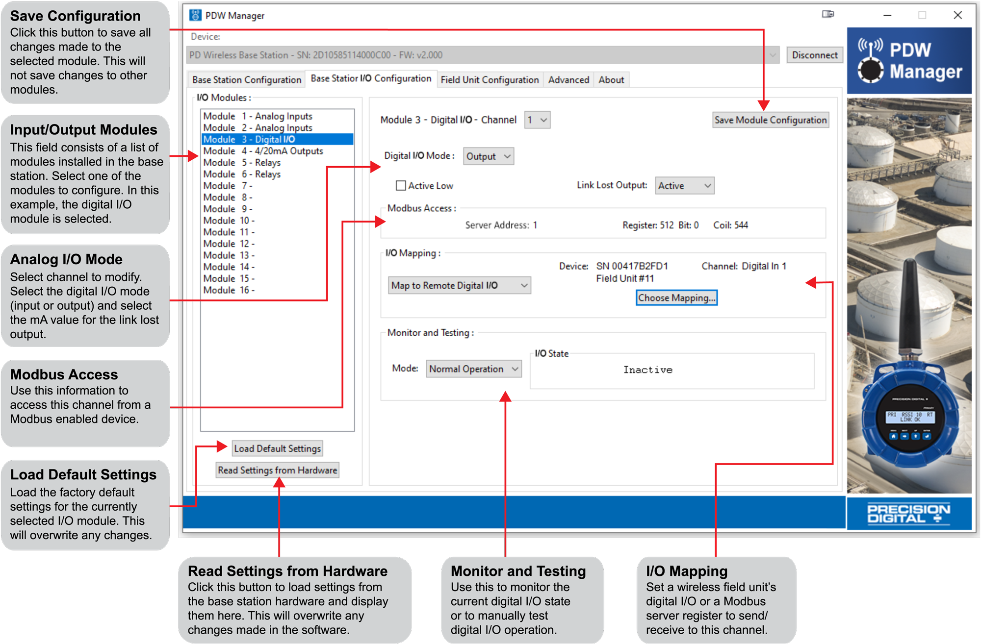
Note: For information about Modbus Access, please see Modbus Register Address vs Modbus Register.
Dual Relay Base Station Module
Each Relays module has two channels. Each channel may be independently programmed and mapped to remote digital I/O or Modbus registers. Once the module’s settings have been modified, click the Save Module Configuration button to save these settings to the base station.
If changes to the module have been made that have not been saved, the settings can be loaded from the base station by clicking the Read Settings from Hardware button. Resetting the selected module to its default settings can be done by clicking the Load Default Settings button.
The Monitoring area at the bottom may be used to view the current relay state or manually test relay operation.
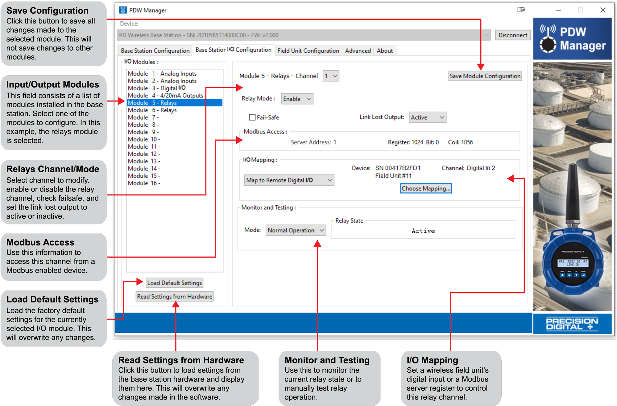
Note: For information about Modbus Access, please see Modbus Register Address vs Modbus Register.
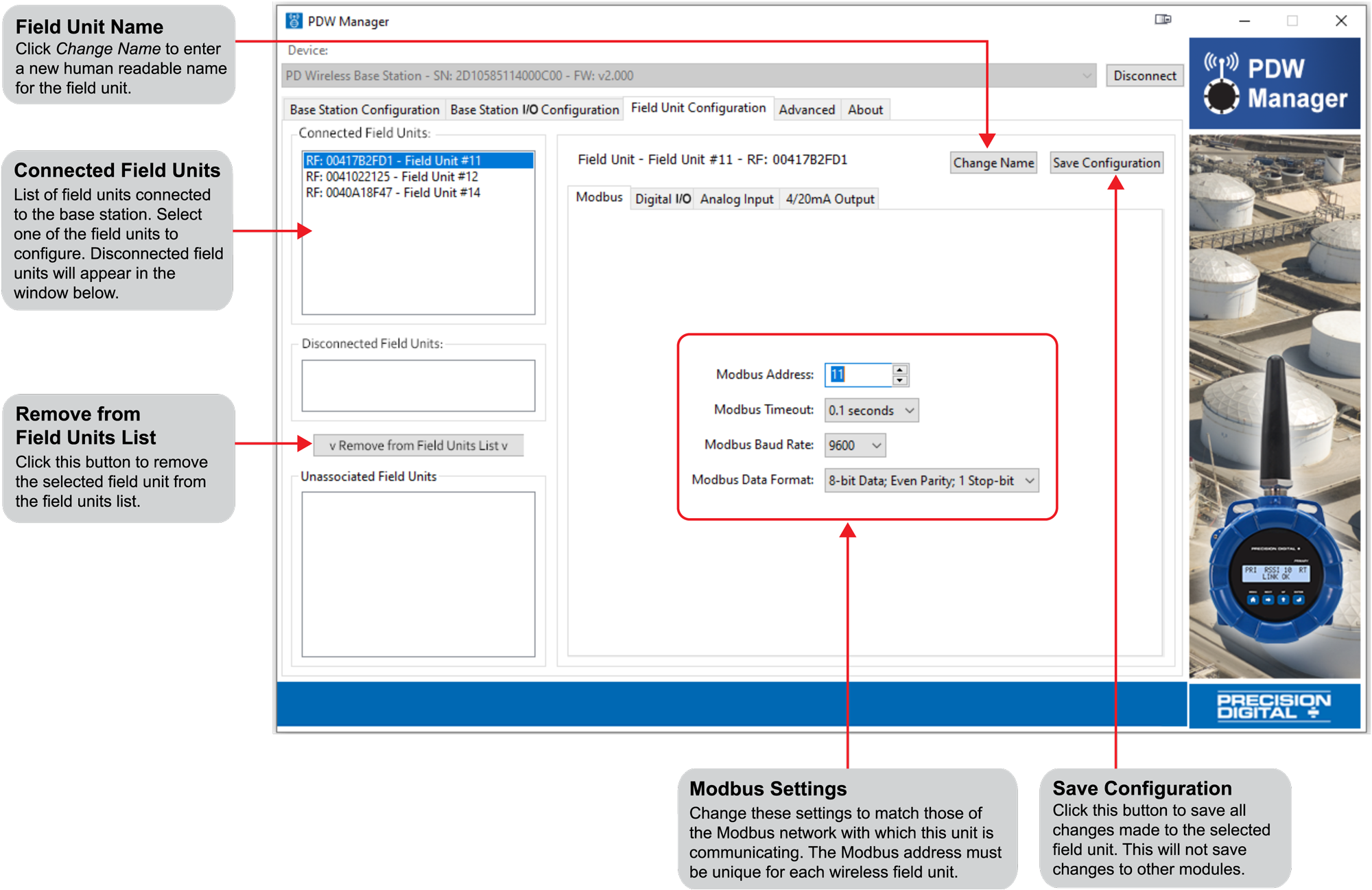
Field Unit Configuration
The Field Unit Configuration tab is where connected field units are programmed to communicate with the base sta-tion. Select a connected field unit from the Connected Clients list in order to begin programming that unit.
A field unit’s human readable name is changed by clicking the Change Name button. Be sure to give each field unit a descriptive name, such as the location of the unit in your facility or the devices connected to it, in order to make future programming easier.
Analog Input
Each field unit’s analog input is programmed to accept a 4-20 mA, 0-10 V, 0-5 V, or 1-5 V signal. Once the module’s settings have been modified, click the Save Configuration button to save these settings to the field unit.
The I/O Mapping section will show to what (if any) device the analog input has been mapped. The Monitoring section at the bottom is used to view the current analog input reading or manually test analog input operation.
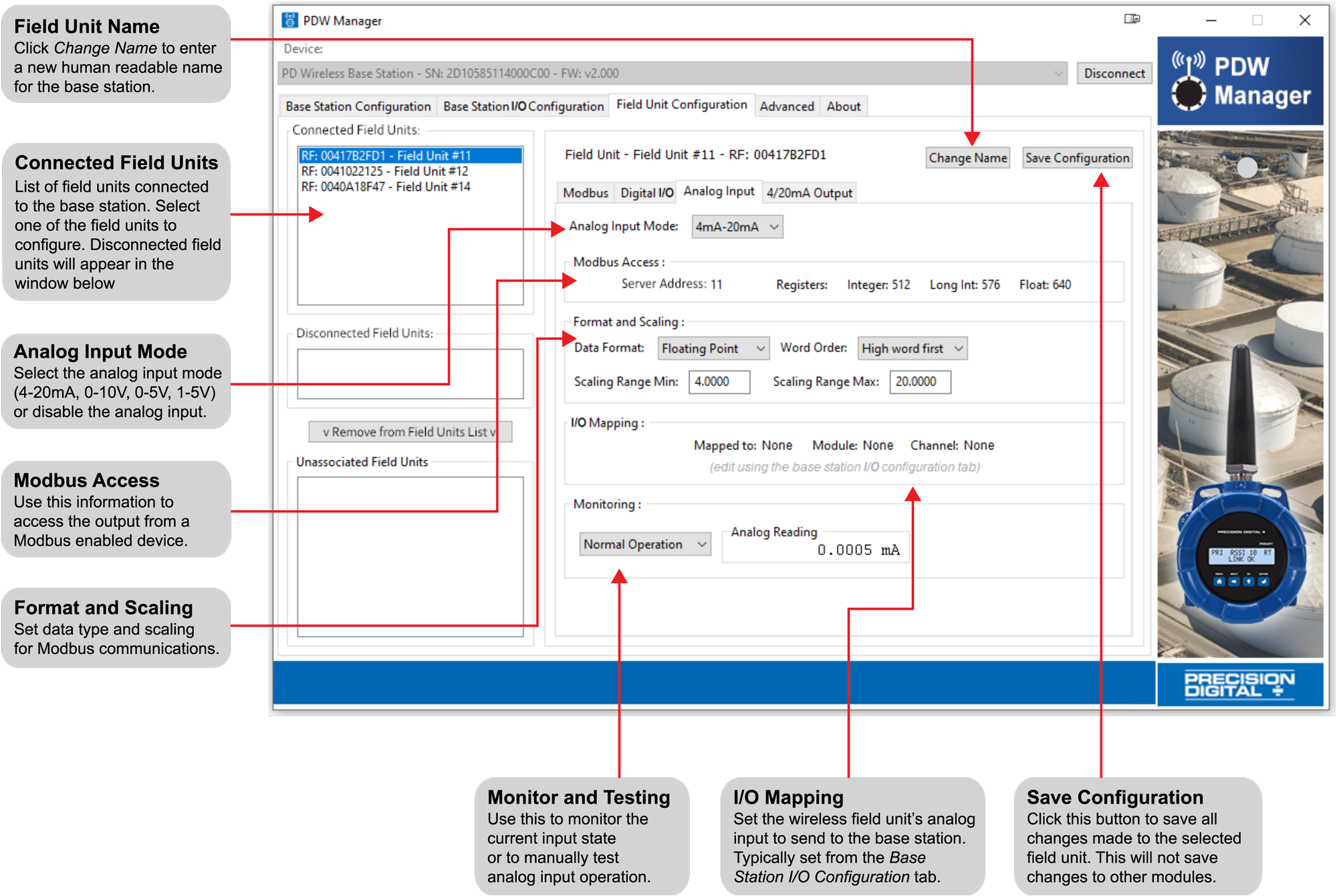
Note: For information about Modbus Access, please see Modbus Register Address vs Modbus Register.
4-20 mA Analog Output
The 4/20mA Output tab is used to program the selected field unit’s analog output. Once the module’s settings have been modified, click the Save Configuration button to save these settings to the field unit.
The I/O Mapping section will show to what (if any) device the analog input has been mapped.
The Monitoring and Testing section is used to monitor the current input state or to manually test analog output operation.
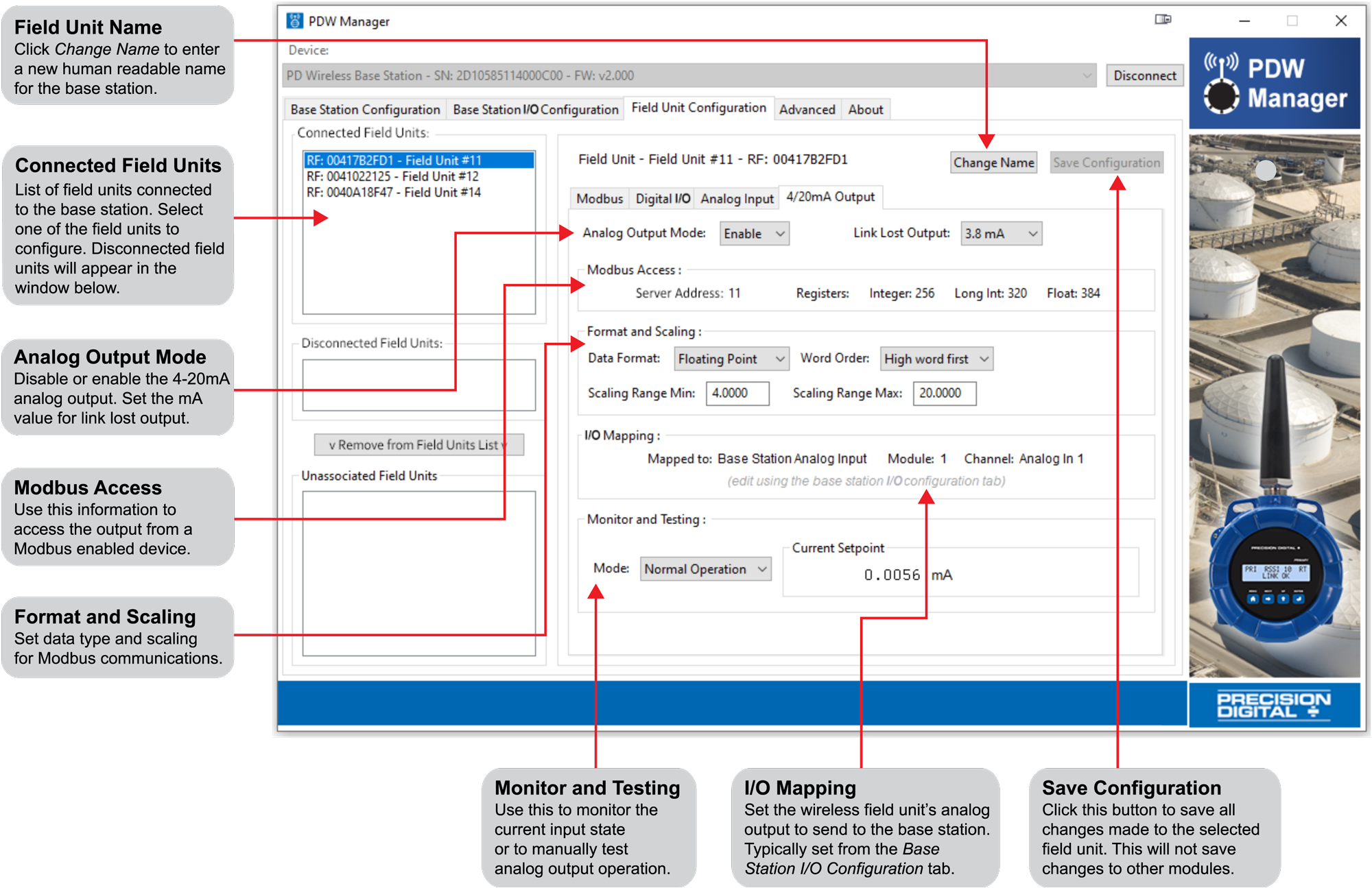
Note: For information about Modbus Access, please see Modbus Register Address vs Modbus Register.
Digital I/O
Each field unit has four digital I/O channels. Each channel can be independently programmed as either an input or an output. Once the module’s settings have been modified, click the Save Configuration button to save these settings to the field unit.
The I/O Mapping section will show to what (if any) device the digital I/O has been mapped.
The Monitoring and Testing section is used to monitor the current digital I/O state or manually test the digital I/O operation.
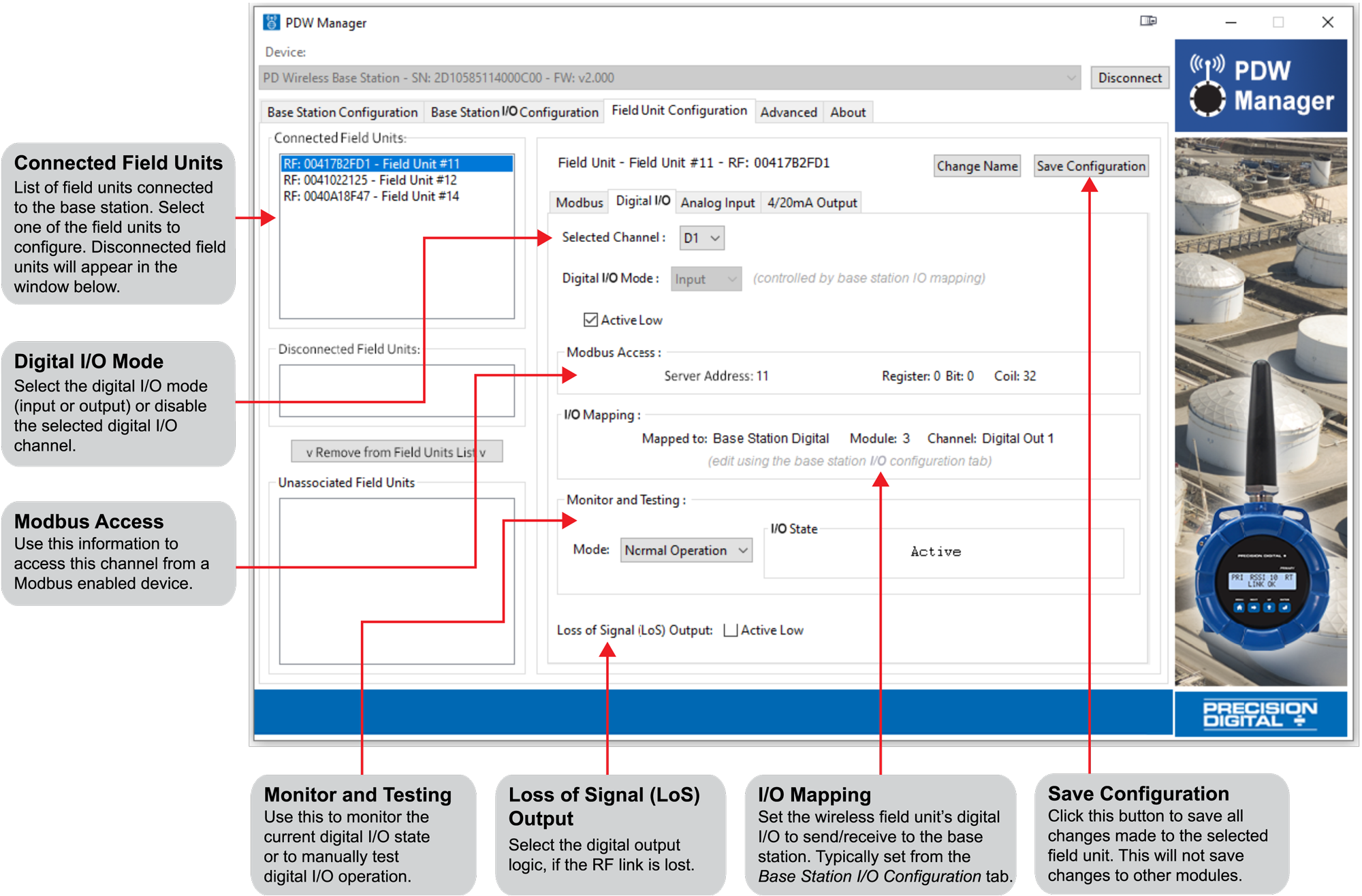
Note: For information about Modbus Access, please see Modbus Register Address vs Modbus Register.
Modbus RTU
Each field unit is capable of transmitting Modbus RTU serial communications. Enter the Modbus network settings on the Modbus tab in order to communicate with the Modbus network. The Modbus address must be unique in order to ensure field unit/base station connectivity.
Once the module’s settings have been modified, click the Save Configuration button to save these settings to the field unit.
Modbus Register Address vs Modbus Register Number
In order to address the wireless units’ Modbus registers, depending on the type of Modbus device, it are necessary to provide either the register address or the register number. PDW Manager shows the register address of input and output devices in the section labeled Modbus Access, as shown below:

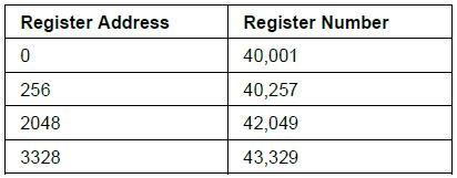
In this example, if the Modbus device requires a register address, use the value 2112 to access the long int value.
If the Modbus device requires a register number, add 40,001 to the register address (in this case: 42,113) to access the long int value. The table at right shows additional register address to register number conversions.
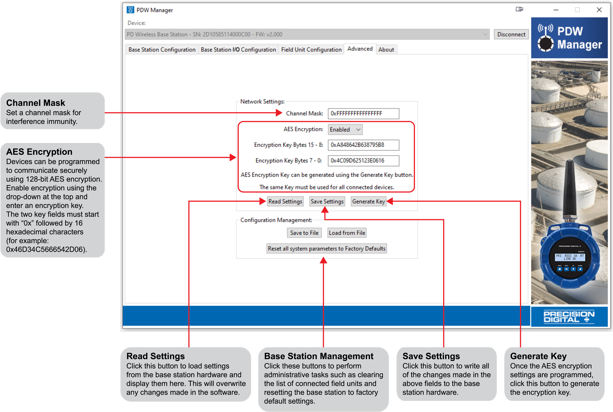
Advanced Configuration for Base Station
Device communication can be secured by enabling 128-bit AES encryption. A channel mask may also be set for interference immunity. The encryption key and channel mask are entered on the Advanced tab. Once the encryption information is entered, click Save Settings.
If changes have been made that have not been saved, the settings can be loaded from the base station by clicking the Read Settings button.
The wireless field units must share identical encryption keys in order to communicate with the base station, so be sure to enter the same information for all of the field units. See Programming the PDW90 Field Units for information on programming the field units.
To reset the base station to factory default settings, click the Reset all system parameters to Factory Defaults button. All field units are removed from the base station data base.
Programming The PDW90 Field Units
The field units can be programmed using the PC based PDW Manager, although it is easier to use the CapTouch through-glass buttons because of the limited number of options available on the field unit. Field units connect to a PC via the micro USB connection on the side of the electronics module, underneath the enclosure cover. Use of PDW Manager is required for programming advanced settings such as digital I/O logic (high or low), loss of signal (LoS) digital output state or analog output value, wireless encryption, and analog signal calibration.
Once the software is running, power the unit using a 9-30 VDC power supply and connect the device to the PC using the provided USB cable.
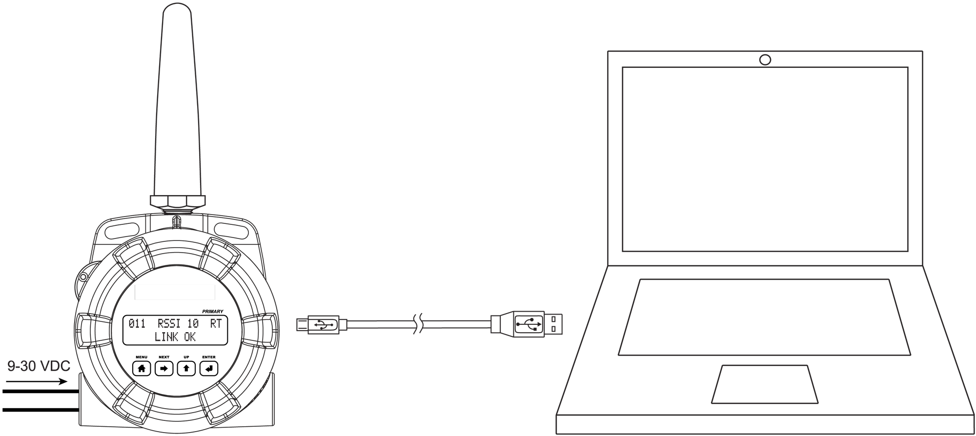
The PC will automatically install the appropriate device drivers. Once this has completed, the device will appear in the Device list at the top of the PDW Manager window. Click Connect.
Configuring the Field Units
The image below shows the available options on the Configuration tab while the field unit is connected.
The network ID, Modbus settings, and password are configured from this tab.
Calibrate the Field Unit’s Analog Input and Output
The field unit’s analog input and output can be calibrated using the Analog Input and 4/20mA Output tabs.
Note: The field units are factory calibrated prior to shipment to read analog input in milliamps and volts depending on the input selection. The calibration equipment is certified to NIST standards.
I/O Testing on the Field Unit
The I/O Testing tab allows for monitoring and testing digital I/O activity, monitoring the analog input and the current 4-20 mA analog output, and displaying the device log’s technical information for testing and debugging purposes.
Advanced Configuration for Field Units

The advanced configuration for field units is accessible only by connecting directly to USB port of the field unit.
Device communication can be secured by enabling 128-bit AES encryption. A channel mask may also be set for interference immunity. The encryption key and channel mask are entered on the Advanced tab. Once you have entered the encryption information, click Save Settings. If changes have been made that have not been saved, the settings can be loaded from the base station by clicking the Read Settings button.
The base station and field units must share identical encryption keys in order to communicate, so be sure to enter the same information for the base station and all of the field units. See Programming the PDW90 Base Station for information on programming the base station
Programming The PDWR Repeater
PDW Manager allows programming of the PDWR wireless repeater unit from a PC with a USB connection. The unit connects to a PC via the micro-USB connection on the side of the electronics module, underneath the enclosure cover. Use of PDW Manager is required for programming advanced settings such as wireless encryption.
Once the software is running, power the unit using a 9-30 VDC power supply and connect the device to the PC using the provided USB cable.

The PC will automatically install the appropriate device drivers. Once this has completed, the device will appear in the Device list at the top of the PDW Manager window. Click Connect.
The image below shows the available options on the Configuration tab while the repeater unit is connected.
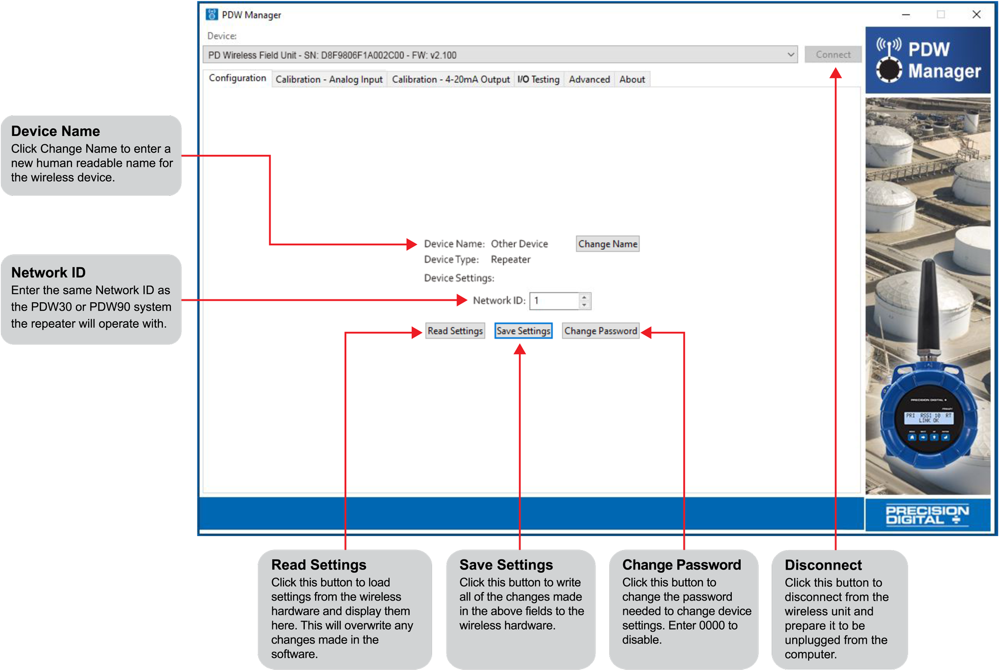
Note: The two Calibration tabs and the I/O Testing tab are not applicable to the repeater unit.
Networking Settings and Security
Device communication can be secured by enabling 128-bit AES encryption. A channel mask may also be set for interference immunity. The encryption key and channel mask may be entered on the Advanced tab.
Once you have entered the encryption information, click Save Settings. The wireless devices must share identical encryption keys in order to communicate, so be sure to enter the same information for the second unit.