
Features
- Field-Mount Pulse Input Flow Rate/Totalizers
- NPN Open Collector, PNP, TTL, Switch Contact, Sine Wave (Magnetic Pickup Coil), or Active Square Wave Inputs
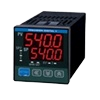
- Top Display: Five 12-Segment Alphanumeric Characters, 0.7" (17.8 mm)
- Bottom Display: Eight 14-Segment Alphanumeric Characters, 0.4" (10.2 mm)
- Display Mountable at 0°, 90°, 180°, & 270° (No Tools Required)
- CapTouch Through-Window Button Programming with Normal and Delayed Modes
- Red Backlight for Alarm Conditions, Enable and Disable Backlight from Menu
- 8-Digit Total & Grand Total Display, Up to 13 Digits Using Both Lines
- Display Rate & Total Simultaneously
- Bi-Directional Flow Detection Via Digital Input
- Non-Resettable Grand Total
- Display Previous Total and Previous Grand Total with Time-of-Day Reset Feature
- Reset Total / Grand Total with CapTouch Button, Digital Input, or Time-of-Day Feature
- Automatic or Manual Batch Control
- K-Factor Calibration or Scaling with Up to 32-Point Linearization
- Gate Function for Rate Display of Slow Pulse Rates
- (2) Open Collector Outputs Standard; Assignable to Pulse, Alarm, Timer, or Stopwatch
- (2) Optional Solid-State Relays; Assignable to Alarm, Sample, Timer, Batch Control, or Stopwatch
- Optional Isolated 4-20 mA Analog Output
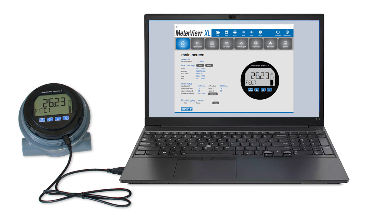
- Free PC-Based MeterView XL USB Programming Software
- 9-30 VDC or 4-20 mA Output Power Options
- Battery-Powered Momentary Backlight & Display Sleep and Off Modes to Extend Battery Life
- Modbus RTU RS-485 Communications Standard on DC & Battery Powered Models
- On-Board Data Logging of up to 2,032 Records and Modbus Accessible Data
- Password Protection for Settings, Total & Grand Total
- Operating Temperature Range: -40 to 167°F (-40 to 75°C)
- Conformal Coated PCBs for Dust & Humidity Protection
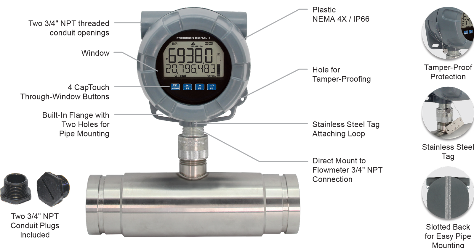
- Flange for Wall or Pipe Mounting; Loop for Stainless Steel Tag; Holes for Tamper-Proof Seal
- Plastic NEMA 4X, IP66 Enclosure with ¾" Connections
- Three 3/4" NPT Threaded Conduit Openings (Two Plugs Included)
- 3-Year Warranty
Overview
General Purpose Pulse Input Flow Rate/Totalizers with Advanced Display and Control
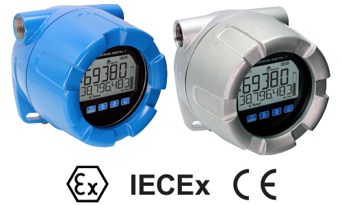
The PD6938 VantageView+ pulse input flow rate/totalizers can be installed in a variety of areas (dirty, wet, corrosive, hot, or cold) to provide convenient and informative display of flow rate and total from any pulse output flowmeter. These instruments will accept a variety of pulse inputs, including slow pulse rates. They can be powered from a battery, 9-30 VDC, or the 4-20 mA output loop, have on-board datalogging capabilities, and can be ordered with optional 4-20 mA output and two relays.
The PD6938, with the addition of its two optional relays, can also be used as a simple batch controller.
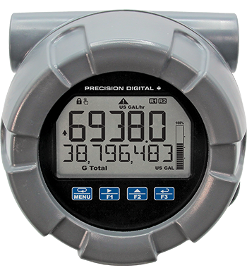
One of the most convenient features of these instruments is their dual-line display, which is typically used to display the flow rate on the top display and flow total, flow grand total, or a tag on the bottom display. The top display has five characters and the bottom display has eight characters for clear indication of tags, units, or alarm messages. Further enhancing the display on these instruments is a 20-segment bargraph and backlighting that can turn red during an alarm condition.
The PD6938 VantageView+ comes in a NEMA 4X, IP66 plastic enclosure that is designed for easy use and installation. There are three 3/4" NPT threaded conduit holes available for wiring. Two 3/4" NPT plastic conduit plugs are included. Field wiring is made to removable screw terminals and the display module can be oriented in 4 different positions to accommodate different mounting configurations and requires no tools to install. The display has been designed to optimize viewing angle.
Free, PC-based, MeterView XL software that connects to the meter via a micro-USB cable is available for programming and setup of the instruments. Four CapTouch through-window buttons are available to operate the instrument without removing the cover.
All models come equipped with two open collector outputs and a digital input. There are also models available with Modbus RTU RS-485 communications, two solid-state relays, and isolated 4-20 mA analog output options. The open collector outputs are useful for alarm indication or pulse output. The digital input can be used to reset the total, to start/stop a timer/stopwatch, to start/stop a batch, and more. The relays can be programmed for alarm indication, on/off control, or simple batch control.
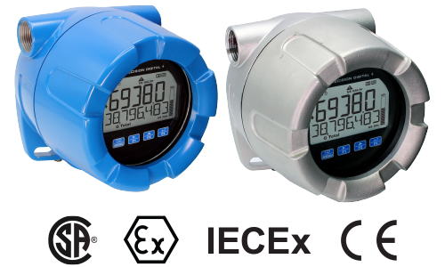
Other PD6938 Models Available
Front
- Flow Rate/Totalizer
- Plastic
Connections
- (2) Open Collector Outputs Standard (150 mA max); Assignable to Pulse, Alarm, Timer, or Stopwatch
- Digital Input for Remote Operation of a Single Task (Reset Total, etc.)
- (2) Loop-Powered Solid-State Relays; Assignable to Alarm, Batch Control, Timer, or Stopwatch
- Isolated 4-20 mA Analog Output
- Modbus RTU RS-485 Communications
Power Options
The PD6938-GP offers power options including battery, DC with battery backup, DC only, output loop, or output loop with battery backups.
Battery Backup
Select models are available with a battery backup power option. For these models, the primary power source is supplied by either DC power or the output loop, depending on the model. The battery is used during battery backup operation. If there is a power failure of the primary power source, the battery will instantly take over powering the meter. There will be no display interruption nor any information loss.
Battery Status Indication
Battery indicators on the display alert users of the power status of the PD6938.
| Indicator | State | Description |
| Flashing | Meter checking battery status | |
| Steady | Meter using battery power | |
| Flashing | Low battery (replace battery) |
Designed for Long Battery Life
| LCD Sleep Mode LCD sleep mode turns the LCD off after a user programmable amount of time, while all inputs and outputs continue working. Press any button for 2 seconds to wake up the display. | |
| CapTouch Delayed Mode In Delayed mode, the buttons enter into a low sensitivity state (sleep) after 20 seconds of inactivity. Press any button for 2 seconds to wake up the buttons. | |
| Momentary Backlight The backlight is enabled by default. If the meter is battery powered, then the backlight is automatically set up to momentarily turn on for 10 seconds when any button is pressed. | |
| Turn Meter Off To extend battery life even more, the meter can be turned off completely when it is not in use. Press and hold the Menu button for 5 seconds to turn the meter on or off and follow the on-screen instructions. |
Display Features
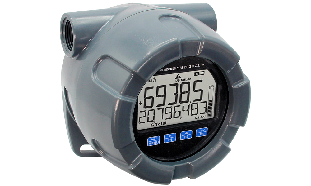
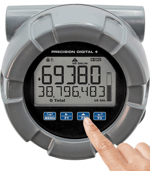
PD6938 Pulse Input Flow Rate/Totalizer with Bargraph
Display Flow Rate & Total at the Same Time
One of the key features of these rate/totalizers is their ability to display flow rate and total at the same time. In addition, the meter can toggle between the rate and total and their corresponding units. The following shows flow rate on the top display and the total flow on the bottom display, both display toggling between values and units.
Wide Variety of Display Capabilities
In addition to the most common setup of flow rate on the top display and flow total on the bottom display, these meters can be set up for a variety of display configurations as shown in the following examples.
See the instruction manual for additional display possibilities for both top and bottom display.
 Flow Rate and Toggle Between Units & Tag
Display flow rate on top, toggle between rate units and tag on bottom
 Flow Total and Toggle Between Units & Tag
Display flow total on top, toggle between total units and tag on bottom
 Flow Total & Flow Grand Total and Toggle Between Units
Display total flow on top and Grand Total flow on bottom, and display toggles between values and units. Notice Grand Total can use different units than Total.
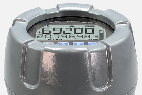
2X More Informative Display
The PD6938 Series display offers a 50% larger display area and is twice more informative than previous generations of loop-powered meters. Featuring an alphanumeric dual-line display and a 20-segment bargraph, reading and understanding process values is easy and intuitive. The addition of status indicators provides a quick glance at alarm conditions, relays, process trends, battery status, and more. Predefined display units give users even more display flexibility.
| Indicator | State | Description |
| Steady | Process trend arrows | |
| Flashing | Alarm indicator | |
| Steady | Password protected | |
| Steady | Solid-state relay 1 | |
| Steady | Solid-state relay 2 | |
| Flashing | CapTouch buttons self-calibrating (wait) | |
| Steady | PV Bargraph | |
| Flashing | Alarm condition: Bargraph segment flashes on alarm | |
| Steady | Displaying Total | |
| Steady | Displaying Grand Total | |
| Steady | Batch is running | |
| Flashing | Automatic batch control: Batch paused or start delayed | |
| Steady | Batch is stopped | |
| Steady | Batch is paused | |
| Flashing | Meter checking battery status | |
| Steady | Meter using battery power | |
| Flashing | Low battery (replace battery) |
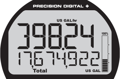
Commas Make it Easy to Read Big Numbers
The bottom display is set to show a comma separating the thousands and millions place by default if a numeric value is being displayed. This feature can be disabled or enabled using the Comma menu.
Using 13 Digits to Display Total
The top and bottom displays can be setup to display a 13-digit total (9,999,999,999,999). The total will roll over to zero when it exceeds the limit.
Red, Flashing Display When Alarms Occur
When an alarm occurs, the display can be programmed to turn red, flash, and display an alarm indicator .
In addition, a unique custom alarm message for each of the two relays and two open collectors can be displayed on the bottom display. These features can be activated even if no relay or open collector is connected.
Backlight Turns Red on Alarm
The backlight is standard on all VantageView+ meters. It provides optimum visibility in any lighting condition and it can be programmed to turn red for alarm conditions. The backlight may be enabled or disabled using the Backlight menu. The backlight is enabled by default. If the meter is DC powered, then the backlight is constantly on. If the meter is battery powered, then the backlight is on according to the setting selected under the System – Battery - Display menu.
Bargraph Provides Quick Understanding
The 20-segment bargraph helps users get a quick understanding of where their process is at. The bargraph can be programmed to represent either rate, a percentage of the rate, total, or it can be disabled.
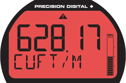
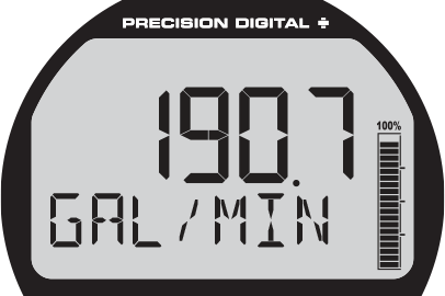
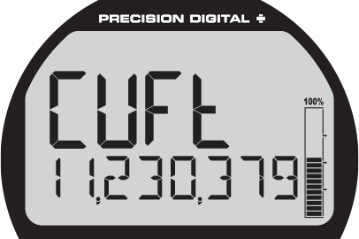
Dual-Scale Display Feature
Users can use the dual-scale feature when they want to show the same input in two different scales. For instance, the example above shows an application where the meter displays the input in gallons per minute and cubic feet per minute.
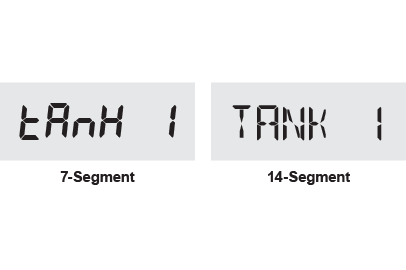
14-Segment Characters
Notice how much better letters like “T”, “N” and “K” appear as 14-segment characters on the bottom display vs. 7-segment characters found on other meters.
Max/Min Display
The max & min readings (peak & valley) reached by the process can be displayed either continuously or momentarily.
- Display momentarily by pressing the F1 function key (default) or assigning to any of the other function keys or to the digital input in the User menu. Press Enter to lock/unlock max/min display.
- Display continuously by assigning either display line to max/min through the Display menu.
Any of the F1-F3 function keys (buttons) and the digital input can be programmed to reset the max & min readings.
Predefined and Custom Units
The meter has the most common predefined rate and volume units. If the desired unit is not available, the user can program a custom unit.
Total & Rate in Different Units
The user can select to display total in different units than the rate. For instance, a customer could measure flow rate in gallons per minute and total in acre-feet by simply selecting AF (acre-feet) units for the total. Additionally the user can enter a custom unit and conversion factor to display the total in any unit of measure.
CapTouch Through-Window Buttons
All PD6938 meters are equipped with four capacitive sensors that operate as through-window buttons so that they can be operated without removing the cover (and exposing the electronics) in harsh environments.
CapTouch buttons are designed to work under any lighting condition and to protect against false triggering. They can be turned off for security via a switch on the display module
To actuate a button, press one finger to the window directly over the marked button area. When the cover is removed, the CapTouch buttons can be used after the meter completes a self-calibrating routine ( flashes). The sensors are disabled when more than one button is pressed, and they will automatically re-enable after a few seconds ( off).
CapTouch Key Features
Capacitive touch technology
More reliable & responsive
Two modes of operation
Operate meter without removing the cover
CapTouch Buttons Operation Modes
The CapTouch buttons have two modes of operation: Normal and Delayed.
NormalNormal is the factory default setting. This mode is recommended for programming the meter or when immediate operation of the buttons is needed.
DelayedUse the Delayed mode to prevent accidental trigger of the buttons. In the Delayed mode, the buttons enter into a low sensitivity state (sleep) and they ignore quick button presses after 20 seconds of inactivity. To wake up the buttons, press and hold any button for more than 2 seconds, the buttons respond normally.
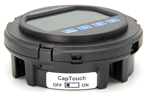
Turning Off CapTouch Buttons
The CapTouch buttons can be turned off for security by moving the slide switch located on the display module to the Off position.
Outputs
PD6938 meters come with two open collector outputs as standard and two solid-state relays and 4-20 mA output as options. The open collector outputs and relays generally operate in the same manner, with the major exception being the open collectors are not available for batch control and the relays are not available with pulse output features. The open collectors and relays can be controlled either automatically or manually. The alarm status (with a unique flashing red message for each of the two relays and open collectors) will show on the display even with no output wired.
Two Open Collector Outputs
The meter is equipped with two NPN open collector outputs that may be set up for pulse outputs, alarms, timed pulses, stopwatch on/off, or disabled. Pulse outputs can be set to transmit the rate, total or grand total. Output 2 may be used to generate a quadrature output based on the other open collector output. An output test mode is also selectable to generate pulses at a constant programmable frequency. The open collectors are commonly used to generate a pulse for every user-defined amount of flow that has been generated. For instance, the meter can be programmed to generate a pulse for every 100 gallons of flow.
Two Optional Solid-State Relays
The meter is optionally equipped with two solid-state relays that may be set up for alarms, sample, timer, batch control, or stopwatch. The relays are rated at 250 VAC/DC @ 0.5 A for resistive loads and 38 VA @ 0.3 A, 250 VAC/DC max (Safe Area only) for inductive loads. Alarms are available based on the PV value or the digital input.
Optional Isolated 4-20 mA Output
The isolated analog output signal can be configured to represent the process variable (flow rate, total, or retransmit). While the output is nominally 4-20 mA, the signal will accurately accommodate under- and over-ranges from 1 to 23 mA. The output can be reverse scaled such that the meter’s high calibration value outputs 4 mA and the meter’s low calibration outputs 20 mA.
Sampling Relay
A relay set to sample will trigger when the total or grand total value has incremented by a programmed amount. The relay can be programmed to stay on for a specified amount of time. For example: if a relay is set to sample the total with a COUNT of 1,000 and a TIME of 10 seconds, the relay will energize for 10 seconds each time the total increments by 1,000 (e.g. 1000, 2000, 3000).
Resetting the Open Collectors and Relays
The open collectors and relays (alarms) may be programmed to reset in the following ways:
- Automatic (AUTO): Alarm will reset automatically once the alarm condition has cleared.
- Automatic/Manual (AUTO.MAN): Alarm will reset automatically once the alarm condition has cleared but can also be reset using the Enter button (or whichever function key is set to acknowledge) at any time.
- Latching (LATCH): Alarm must be reset manually and can be done so at any time. Press the Enter (ACK) button at any time to clear the alarm.
- Latching with Reset after Cleared (L-CLEAR): Alarm must be reset manually and can only be done so after the alarm condition has cleared. Press the Enter (ACK) button after the alarm condition has cleared to reset the alarm.
Timer Function
Timers are used in everyday life; one of the most common examples is the microwave oven. Industrial timers are used in process control applications where certain events or actions need to be controlled by time. Examples include automatic batch control applications, where the relay needs to be energized for a specific length of time.
The timer fuction is available on the open collector and relay outputs; which means that you can have up to four timers per meter. The start and stop actions can be triggered from the setup menu or by the function keys and digital input. The meter can be setup to display the off/on timer count down.
There are two modes of operation:
- Continuous Timer (Interval)
At the start of the timer the output is off and turns on after the Off Delay elapses. The output remains on for the duration of the On Time. The cycle repeats until the user stops the timer either from the menu or a function key. - One-Shot Timer
At the start of the timer the output is off and turns on after the Off Delay elapses. The output remains on for the duration of the On Time. The timer stops and the cycle does not repeat.

- A sensor detects the bottle is in place and triggers the digital input to start the timer
- The timer output controls the filling pump
- The On Time is set according to the time needed to fill the bottle
Batch Control
The PD6938, when ordered with the two solid-state relays, can be used as a simple, one or two-stage batch controller. The user enters a preset and preclose value and sets the meter to either count up or count down. The top display will show the total and the bottom display will show the preset batch amount. The function keys are automatically changed so that F1 starts a batch, F2 opens the preset menu to allow the preset value to be changed, and F3 pauses/stops the currently running batch. Batching can be either automatic or manual.
Batch Control Operation Example
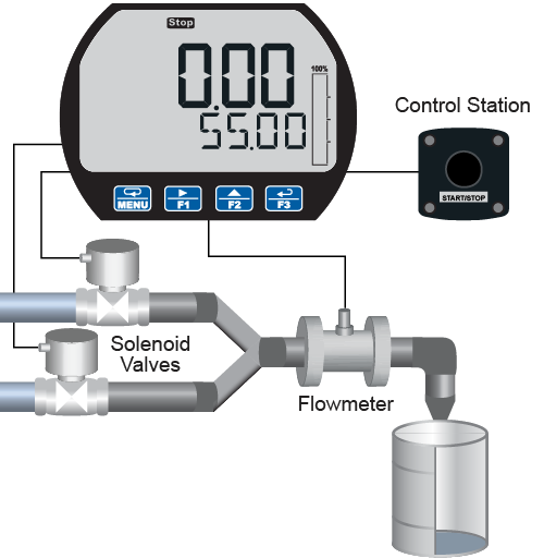
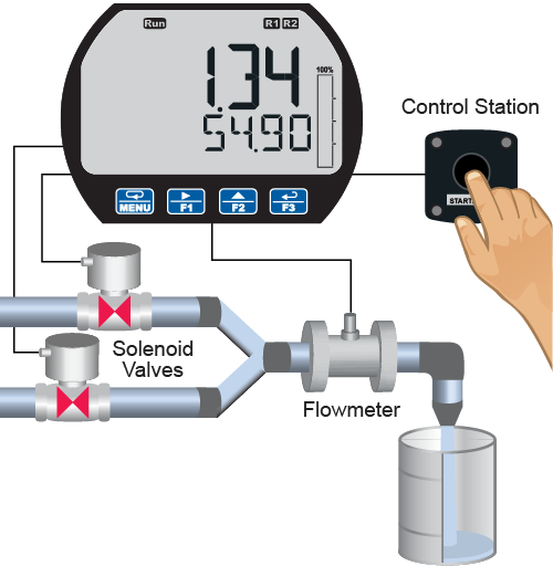
The following example shows how two-stage manual batch control functions with a PD6938. This setup will establish a 55-gallon preset for the batch, with a main valve (high flow) that will close at 50 gallons, and a trickle valve (low or restricted flow) that will close at 55 gallons. Because the first batch overruns by 0.10, the batch preset will be changed to 54.90 for the next batch to compensate for overrun.
If only one-stage batch control is desired, do not assign relay 2 to batch. The following pages show illustrations of how the above settings control the batch operation. The display assignment shown is the default.
| Parameter | Setting | Function |
| RELAY OUTPUT 1 | RLY 1 BATCH | Press Enter to assign relay 1 batch parameters. |
| BATCH COUNT | UP or DOWN | Setup batch to count up or down. |
| BATCH MAXIMUM | 100.00 GAL | This setting prevents the operator from entering a preset value that exceeds a safety limit for the batch process. |
| BATCH MODE | MANUAL or AUTO | Press Enter to select manual or automatic batch control. |
| BATCH PRESET | 55.00 GAL | Enter the batch size. |
| BATCH DELAY | ON & OFF | Enter the On & Off time delays for relay 1, if desired. |
| Parameter | Setting | Function |
| RELAY OUTPUT 2 | RLY 2 BATCH | Press Enter to assign relay 2 batch parameters. |
| BATCH PRECLOSE | YES PRECLOSE 5.00 | Set the pre-close value to 5 to close the valve being controlled by relay 2 so it closes five gallons before reaching the preset. |
| BATCH DELAY | ON & OFF | Enter the On & Off time delays for relay 2, if desired. |
| RELAY MESSAGE | MSG RELAY 1 | Enter a message to be displayed while relay 1 is on, if desired. |
| MSG RELAY 2 | Enter a message to be displayed while relay 2 is on, if desired. |
Manual Batch Control
The manual batch control feature is used for batch processes that the operator wants to start manually. It can also be used where the batch size needs to be manually adjusted for each batch. The batch can be controlled by the button on the meter or the digital input.
System Setup
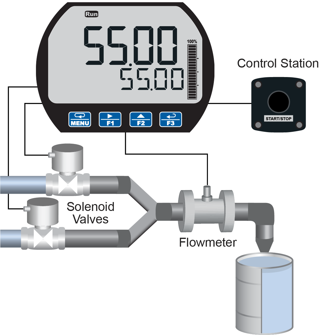
Both valves are closed with an empty barrel in place. The batched total is displayed in the upper display, the preset is selected for the lower display.
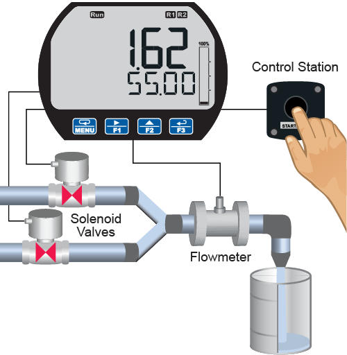
Batch Start
The START button or (F1) is pressed. Both valves open. The barrel begins to fill.
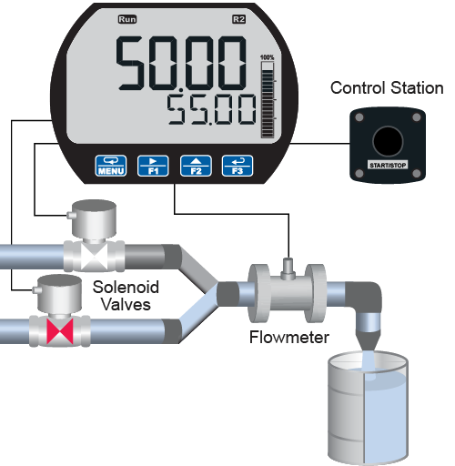
Preclose Valve
When the batch total reaches a value of 50.00 (Preset [55.00] – Pre-close [5.00]) the full-flow valve closes. The fill rate of the tank slows as a result.
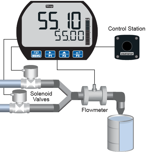
Completed Batch
When the batch is complete, the restricted flow valve closes. If overrun occurs, then the preset must be adjusted to compensate for the overrun amount. The next batch will only start after the START button or (F1) is pressed.
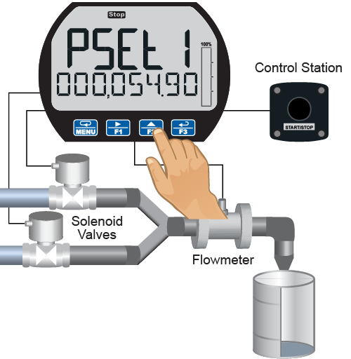
Overrun Correction
To compensate for overrun in the previous batch, adjust the preset to 54.90, so that the next batch is accurate (55.00).
Manual Start of Next Batch
A new, empty, barrel is put in place and the START button or (F1) is pushed to manually start the next batch.
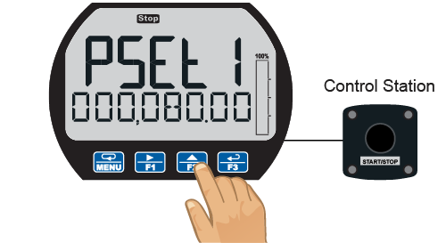
Change Batch Size
While the process is stopped, a new preset fill amount may be selected with the Batch key (F2) for a different size barrel.
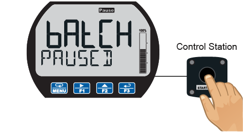
Pause/Stop
At any time, press the STOP button or Stop key (F3) once to pause the process, or twice to cancel the batch, which stops the process.
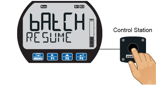
Resume Batch
If the batch has been paused, then press START button or (F1) to resume the batch process.
Automatic Batch Control
The automatic batch control feature is used for batches that start automatically once the previous batch is completed. There is no opportunity for the operator to change the batch size between batches. The batch can be controlled by the button on the meter or the digital input.
System Setup
Both valves are closed with an empty barrel in place. The batched total is displayed in the upper display, the preset is selected for the lower display.
Batch Start
The START button or (F1) is pressed. Both valves open. The barrel begins to fill.
Preclose Valve
When the batch total reaches a value of 50.00 (Preset [55.00] – Pre-close [5.00]) the full-flow valve closes. The fill rate of the tank slows as a result.
Completed Batch
When the batch is complete, the restricted flow valve closes. If overrun occurs, then the preset must be adjusted to compensate for the overrun amount.
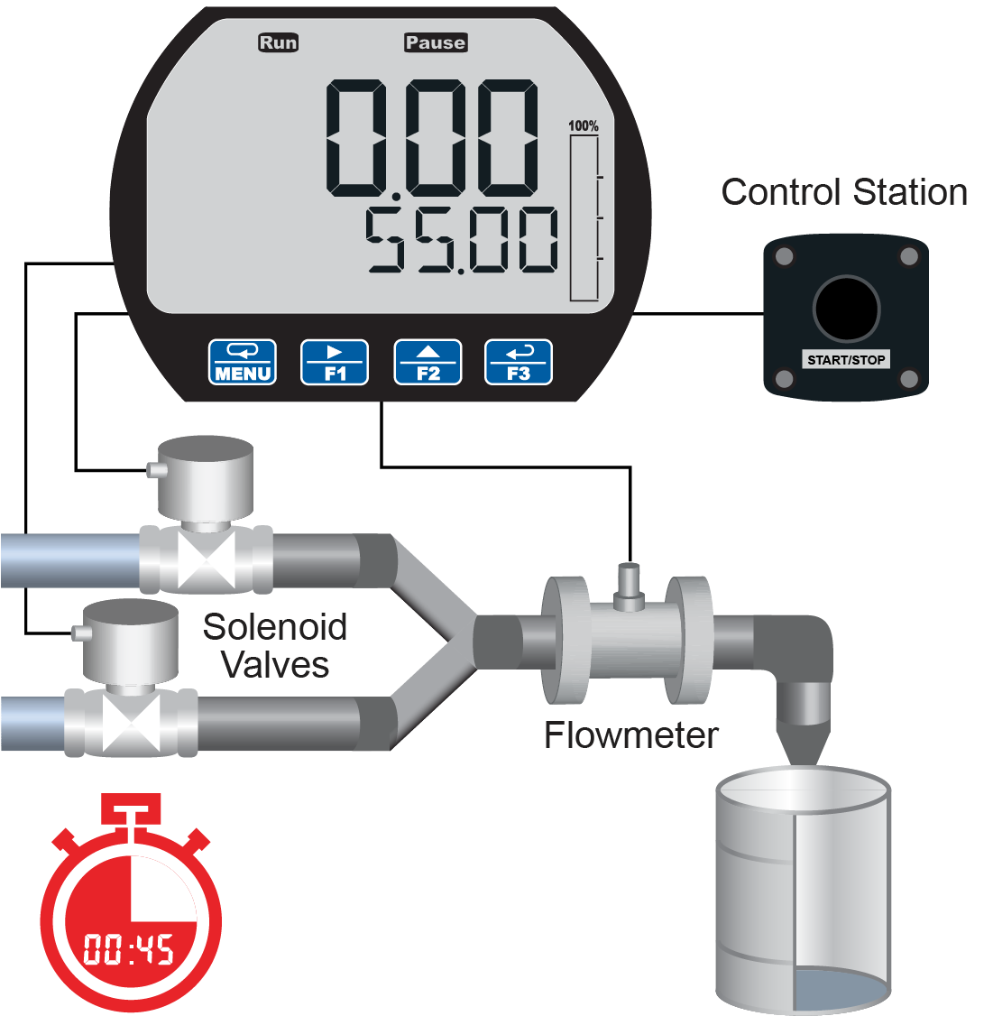
Start Delay
After the batch is completed, the operator removes the full barrel and places an empty barrel; the new batch starts automatically after 60 seconds (Time Delay).
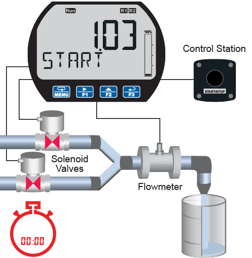
Automatic Start of Next Batch
The next batch begins automatically after 60 seconds, both relays activate and both valves open.

Pause
At any time, press the STOP button or Stop key (F3) once to pause the process.

Resume Batch
If the batch has been paused, then press START button or (F1) to resume the batch process.
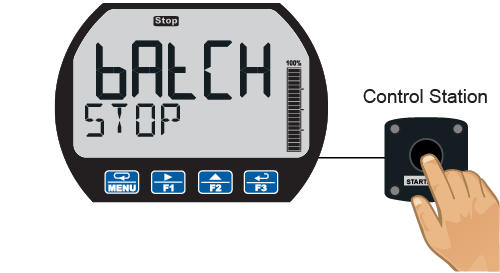
Stop Process
At the end of the shift, press STOP button or Stop key (F3) twice to stop the batch process.
Totalizer Capabilities
PD6938 flow rate/totalizers can be programmed for a wide variety of totalizer applications. They can display total, grand total, or non-resettable grand total; the rate can be displayed with a time base of seconds, minutes, hours or days. The user can program a totalizer conversion factor, a non-resettable grand total, password protection, and several total reset methods.
8-Digit Total & Grand Total Display, Up to 13 Digits Using Both Lines
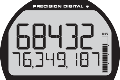
The flow rate/totalizer can be programmed to show eight full digits of total on the bottom display or 13 digits of total using both the top and bottom displays. In both cases, the display can be programmed to include commas to make it easier to read the very large numbers; ie 44,987,356.
In 13-digit mode, the bottom line shows the least significant digits and the top line shows the most significant digits. The meter is not capable of displaying commas on the top line, so this number is actually 1,211,230,379. The commas can be removed from bottom if desired. See sample on bottom, right.
 8 Digits of Total on Bottom
 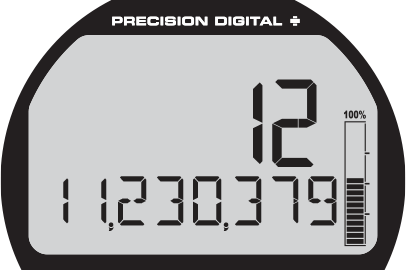 In 13-Digit Mode
Totalizer Conversion Factor & Multiplier
The user can enter a totalizer conversion factor that allows the meter to display total in different units than the rate. For instance, a customer could measure flow rate in gallons per minute and total in millions of gallons. A multiplier may be selected to automatically display the value in kGAL, MGAL, etc. Use the custom units to display the total in any unit of measure including units in languages other than English.
Total Alarms
The two open collectors and the two relays can be set up to alarm when the total reaches a user-defined set point. A variety of reset modes are available and the user can also program time delays and fail-safe operation.
Totalizer Password Protection
The total and grand total can be password protected so they can be reset only by authorized personnel.
Total Stored in Non-Volatile Memory
Total and grand total values, and all programmed settings are stored in non-volatile memory for a minimum of ten years if power is lost.
Front Panel Total Reset
The three front panel function keys can be programmed to reset the total and grand total. This makes it possible for the user to reset either the total or the grand total by pressing the appropriate function key. Of course, if the total or grand total is password protected, they will not reset when the function key is pressed unless the password is entered.
Non-Resettable Grand Total
The user can set up the grand total to be non-resettable by selecting YES for PERMLOCK in the Advanced - Grand Total - Reset menu. Once this is done, the grand total can never be reset.
Low-Flow Cutoff
The user may program the meter for a low-flow cutoff such that the meter displays zero below this point, regardless of the input value.
Remote Total Reset
The total can be reset via an external contact closure on the digital input.
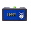
For more information about control stations, please see PDA2360 Plastic Control Stations.
Advanced Features
Automatic K-Factor Unit Calibration
The meter may be scaled using the K-Factor, or conversion factor, function. Most flowmeter manufacturers provide this information with the device. Enter the K-Factor menu and select the units defined with the K-Factor (example: pulses/gal), the decimal point with highest resolution possible, and program the K-Factor value. The meter automatically calculates the flow rate using the K-Factor value and the units selected. The rate can be displayed in any time-base and decimal point resolution selected in the Display menu.
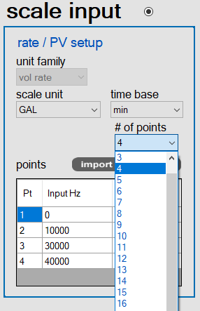
Custom Scaling and Live Input Calibration
Instead of K-Factor setup, the meter can be scaled to any span relative to the input pulse rate span (i.e. if you knew the pulse input span for gallons but wanted to display the rate and total in liters). No external signal is required.
Live input calibration can also be performed. This is done at any two points along the scale. Using this method, an operator can set a “best fit straight line” for nonlinear input spans.
Gate Function for Slow or Unsteady Pulses
The gate function allows for a rate display of slow or unsteady pulse rates. Using the programmable gate, the meter is able to display pulse rates as slow as 1 pulse every 9,999 seconds (0.0001 Hz). The gate function can also be used to obtain a steady display reading with a fluctuating input signal. There are two settings for the Gate, low gate and high gate.
Modbus® RTU Serial Communications
Select PD6938 models are available with Modbus RTU RS-485 communications and can communicate with any Modbus master device. Below are just some of the actions you can perform using Modbus.
- Read rate, total, grand total, max, and min display values
- Read the on-board 2,032 record data log
- Access all parameters remotely for programming or verification
Multi-Point Linearization
Meters are set up at the factory for linear function with 2-point linearization. Up to 32 linearization points can be selected for rate under the linear function. Multi-point linearization can be used to linearize the input for non-linear signals to convert level to flow using weirs and flumes with complex equations.
MeterView XL software makes it easy to program up to 32 points.
Bi-Directional Flow
The PD6938 can be set up to process bi-directional flow by connecting the bi-directional switch from the flowmeter to the meter's digital input (DI) terminals, setting up the digital input to activate the flow function (Reversed or Forward), disabling the low-flow cutoff feature, and enabling negative count (if the total is expected to go negative).
Data Logging
The PD6938 is capable of data logging up to 2,032 records, each containing date, time, rate, total, grand total, relay & open collector states. The user can choose what information to log, when, and how to log it. The log file can be downloaded using the MeterView XL software and it can be saved in .csv file format.
Real Time Logging
A real time clock records the date and time for each data log entry. The data may be recorded using the Log Time feature up to 4 times per day at specific times entered by the user. When the log is full, it will roll over and continue to log, deleting the oldest data. The data may also be recorded using the Log Interval feature, recording the data every programmed time interval, from 1 minute to 24 hours.
When the Interval log is full, recording will stop, keeping all data until logging is started again.

Easy On-Screen Access
The data log entries are easily viewable on the meter LCD. Data points may be navigated by viewing the date and time, rate, total, or grand total amounts. A known log may be jumped to immediately, avoiding a lengthy search for data. With through-window buttons and a customizable menu, the data log can be accessed quickly and without the need for external control stations or serial communications, for easy viewing in the field.
Data Log Setup with MeterView XL
The easiest way to set up the data logger is using the MeterView XL software connected via the micro-USB port or the RS-485 Modbus connection. There are many ways to log data using the on-board memory. Use the MeterView XL software to download the data or a Modbus application.
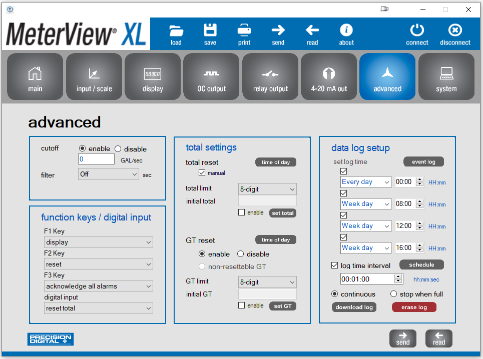
- Log time: Every day or any day of the week
- Log time interval: Select the logging interval
- Select to log continuously or stop when full
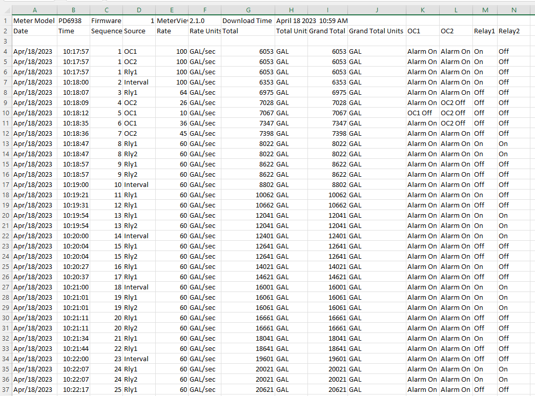
Data Log Example
The log file is saved in .csv file format and it contains all the information selected in the data log setup.
Physical Features
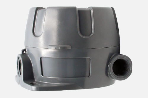
VantageView+ Plastic Enclosure
NEMA 4X Enclosure
The VantageView+ enclosure provides serious protection from the elements, high impact, corrosion, and dust. It is NEMA 4X/IP66 rated.
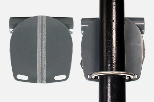
Easy Pipe Mounting
The VantageView+ comes with a built-in flange. This allows easy mounting to walls or pipes using either a PDA6846 Zinc Plated Steel or a PDA6846-SS Stainless Steel 2" U-Bolt Kit. A slot on the back of the enclosure makes it easy to center the unit on a pipe.
Wide Viewing Angle
The window and display module have been optimized to provide a wide viewing angle of approximately ±40°; nearly twice that of the competition.
Tamper-Proof Capability
The instrument can be made tamper-proof by inserting a wire through the built-in loop on the base of the enclosure and a hole in the lid of the enclosure and securing this wire with a lead seal.
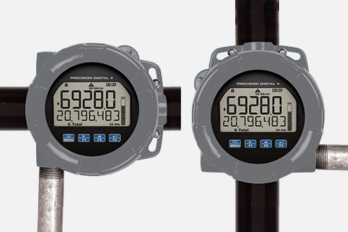
Rotatable Display Module
The display module can be rotated in 90° increments providing added mounting flexibility. Plus the various conduit connections allow a variety of installation options.
Stainless Steel Tag Attaching Loop
The enclosure is equipped with a loop at the top to easily attach a PDA-SSTAG stainless steel tag.
Easy Wiring & Service
The VantageView+ has been designed for easy wiring and servicing. All connections are made to removable screw terminal blocks. There are no exposed printed circuit boards. The display module snaps into the built-in rails on the enclosure ensuring a secure and perfect fit every time. No tools are needed to install or remove it. The options module is screwed into the base of the enclosure. Both modules completely encase the printed circuit boards.
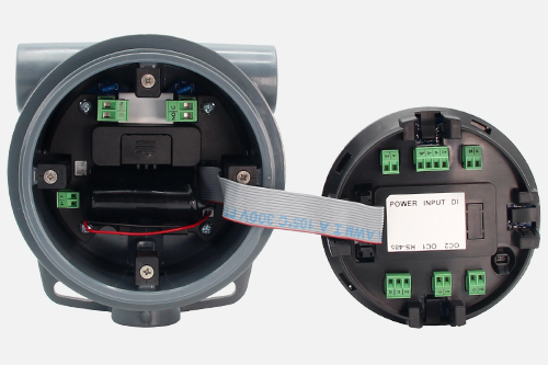 Options module (left) connected to display module (right)
 Options module is mounted on the bottom of the enclosure and the display module is mounted on the built-in rails
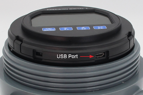
USB Port for Easy Connection to Free MeterView XL Software
A USB port located on the display module allows it to be connected to a PC for use with free MeterView XL software. The meter is powered by the USB connection during programming, if a 4-20 mA loop is not connected.
Three Threaded Conduit Openings
The VantageView+ comes with three 3/4" NPT threaded conduit openings and two conduit plugs included.
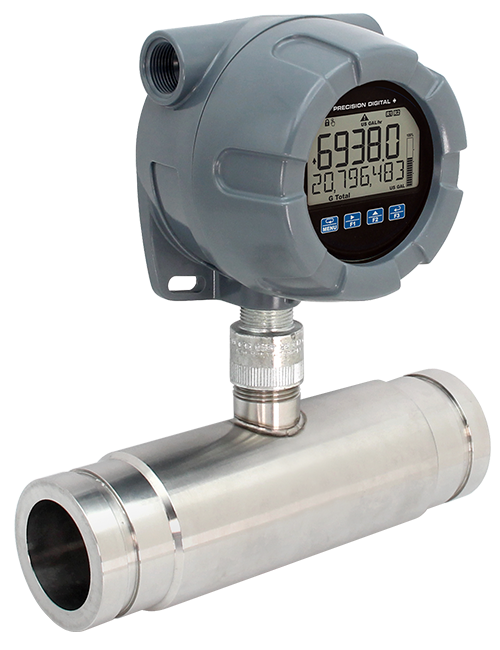
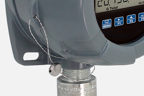
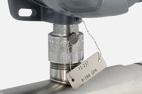
Direct Mounting
The PD6938 features a bottom threaded conduit opening that allows easy mounting directly to a flowmeter. The VantageView+ features a bottom 3/4" NPT conduit opening.
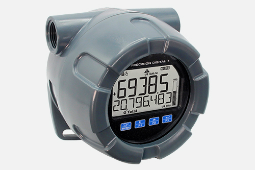
This image shows a battery powered PD6938 mounted to a turbine flowmeter. Even though the unit is battery powered, it has a backlight that turns on only when CapTouch buttons are in use.
Operational Features
There are two ways the user can interact with the VantageView+ to perform a variety of useful functions: programmable function keys and the digital input.
Programmable Function Keys
The three CapTouch buttons labeled F1, F2, and F3 can be programmed as function keys to perform a variety of meter functions simply by pressing on the window over the button. These include resetting the total, operating the batch control functions, resetting the meter’s relays or open collectors, starting and stopping timers, and displaying max/min values. The default settings for the function keys are:
| Button | Description (Default Settings) |
| Press to display grand total. Continue pressing to cycle through max, min, rate, and total displays. | |
| Press to access the Reset menu. Press F1 to scroll through the options. Press F3 to reset the currently displayed parameter. | |
| Press to acknowledge all manually resettable relays or open collectors. Press to lock/unlock the display value after pressing the F1 key. |
On-Board Digital Input
A digital input is standard on VantageView+ meters. This digital input is programmed identically to the function keys. The input is triggered with a contact closure between DI+ and DI-, or with an active low signal. For a complete list of Digital Input settings available, see Function Keys & Digital Input Available Settings in the instruction manual.
Remote Operation of Meter
The VantageView+ digital input can be connected to a PDA2360 single button remote control station and be programmed to perform various functions. Common uses for this digital input would be for resetting the total, operating the batch control functions, resetting the meter’s relays or open collectors, starting and stopping timers, and displaying max/min values.
For more information about control stations, please see PDA2360 Plastic Control Stations.