This form of 4 of 20 mA manual control allows the user to use the Set Point to set the output value of a 4 to 20 mA output. With the scaling established in this note, the user sets what he wants for a mA output using the set point. A SP of 4 will result in the retransmitting output transmitting 4 mA, a SP of 12 will result in the retransmitting output transmitting 12 mA, etc.
Step 1: Retransmission Group Setup
In the Retransmission Group (G.RET), set the retransmitting outputs to be based on the Set Point. To do this, set the rEt parameter to SP as shown in Figure 1.
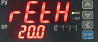
Next, setup the values at which 4 mA and 20 mA will be transmitted. Parameter rEtH establishes at what SP value 20 mA will be transmitted, and rEtL established at what SP value 4 mA will be transmitted. Set rEtH to 20.0 and rEtL to 4.0, as shown in Figures 2 and 3
Figure 1: Set retransmitting output values to be based on SP values |
Figure 2: The SP value when 20 mA will be output by retransmitting outputs |
Figure 3: The SP value when 4 mA will be output by retransmitting outputs |
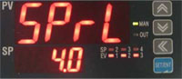
| Step 2: Set Point Setup To restrict the values the Set Point can be set to for use in this application, establish a high and low range the Set Point can be set to. In the Set Point Group (G.SP) establish Set Point range restrictions with parameters SPrH and SPrL. Set parameter SPrH to 20.0 to establish 20.0 as the maximum value the Set Point can be changed to. Set parameter SPrL to 4.0 to establish 4.0 as the minimum value the Set Point can be changed to. These settings are shown in Figures 4 and 5. |
Figure 4: Restricted maximum value the SP may be manually set to | |
| Step 3: Output Configuration Under the Output Group (G.OUT), set the analog output to be used as the 4-20 mA source to be a retransmitting output (ret). This is shown in Figure 6. |
Figure 5: Restricted minimum value the SP may be manually set to | |
| Variations Parameters rEtH, rEtL, SPrH, and SPrL can be altered to allow for different scaling for the 4-20 mA output. For example, if the user wanted to have 4 mA transmitted when the SP is 0, and 20 mA transmitted when the SP is 100, rEtH and SPrH would be set to 100, and rEtL and SPrL would be set to 0. Note however that the set point cannot go higher or lower than the max scaled range of the input scale. For example, if the input is scaled for 0.4 to 2.0 VDC, the set point cannot be set to 0. |
Figure 6: Setting an analog output to be a 4-20 mA retransmitting output | |


Related Products: PD540, PD541, PD542, PD543, PD544, PD545, PD546, PD547, PD548, PD549